Secrets of Airliner Flying 6.3 Final Approach Fix and ILS Setup
In Section 6.1, we covered the aircraft passing the Intermediate Fix (IF) and entering a state of Level Flight.
In this section, we will discuss the operations during the flight from the IF to the Final Approach Fix (FAF).
The relationship between the IF and FAF was introduced in Section 5.4; let’s review that here.
On the NAV/RAD page of the CDU, verify that the entered data is correct,
for example, check the landing Runway azimuth is 128 degrees and the radio frequency is 110.90MHz.
The image below shows a schematic of the Boeing 777 CDU display.

Set the Flaps handle according to the flap deployment plan, such as “Flap 5”, and monitor the extension of the Flaps and slats.
ATC should also be handed over to Tower Control at this time. Continuing with the example of Air System 115 flight from Tokyo Haneda Airport to Hokkaido Sapporo New Chitose Airport.
“Approach: Air System 115, 4 Miles south Hayakita, Contact Tower 118.8 Pilot: Contact Tower 118.8, Air System 115”
The pilot tunes the communication frequency to 118.8MHz and contacts the Tower, “Pilot: Chitose Tower, Air System 115, 2 Miles to Hayakita, Spot 16 Tower: Air System, Tower, Roger, Report Depart Hayakita, Runway 19L, Wind 220 at 12 Pilot: Check Depart Hayakita, 19L, Air System 115” The Tower requires the pilot to contact again after passing the Hayakita reporting point.
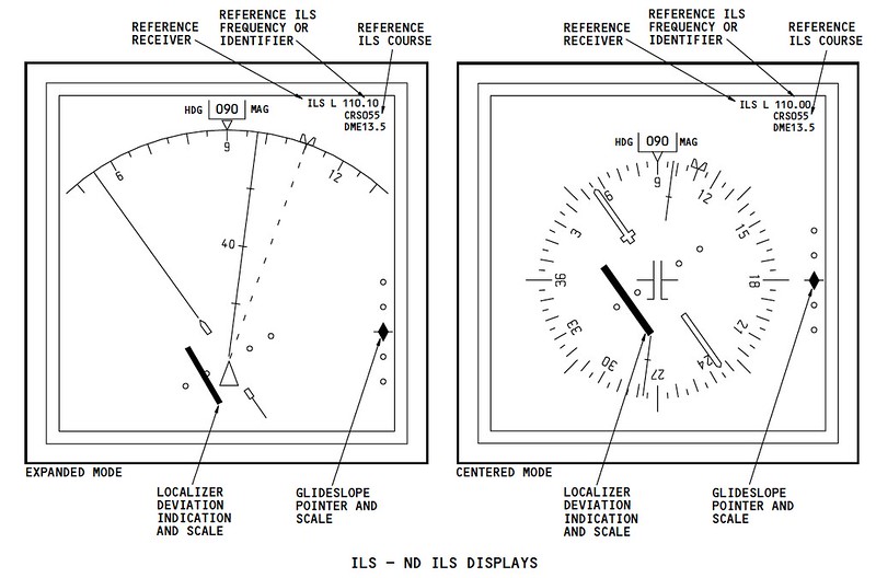
At this point, the Glideslope and Localizer pointers should be displayed on the ND (Navigation Display).
After passing Hayakita, the pilot contacts the Tower, and the Tower instructs the pilot to report again when entering the Base leg. “Pilot: Chitose Tower, Air System, Depart Hayakita Tower: Air System 115, Roger, Report Base, Runway 19L, You are No.1, No Traffic Pilot: Report Base, 19L, We are No. 1, Air System 115”
After reporting entry into the Base leg, the Tower issued a landing clearance. “Pilot: Chitose Tower, Air System 115, Turning Base Tower: Air System 115, Tower, Re-Check Gear Down Cleared to Land, Runway 19L, Wind 220 at 14 Pilot: Cleared to Land, 19L, Air System 115”
The aircraft then enters the Final leg. The pilot engages the APP (Approach) mode on the MCP and starts the second autopilot (turning on the A/P switch for the side that was not active).
Remember that during the landing phase, it is necessary to have both the left (A) and right (B) autopilots engaged simultaneously.
 At this moment, with the aircraft’s lateral attitude management in HDG mode, it can capture the LOC (Localizer) signal,
Therefore, the lateral control on the FMA (Flight Mode Annunciation) displays HDG SEL/LOC status.
Similarly, the vertical control involves both ALT and G/S (Glideslope) acting simultaneously.
At this moment, with the aircraft’s lateral attitude management in HDG mode, it can capture the LOC (Localizer) signal,
Therefore, the lateral control on the FMA (Flight Mode Annunciation) displays HDG SEL/LOC status.
Similarly, the vertical control involves both ALT and G/S (Glideslope) acting simultaneously.
The aircraft begins to intercept the ILS LOC course,
 If all onboard navigation equipment is functioning normally and the Heading and Glideslope can capture the signals transmitted by the ground antennas,
The FMA status will change: the lateral control changes to LOC status, and the vertical control changes to G/S status.
The Blind Landing system (ILS) officially takes over the landing process, tracking the ILS radio waves to control the aircraft’s automatic flight.
If all onboard navigation equipment is functioning normally and the Heading and Glideslope can capture the signals transmitted by the ground antennas,
The FMA status will change: the lateral control changes to LOC status, and the vertical control changes to G/S status.
The Blind Landing system (ILS) officially takes over the landing process, tracking the ILS radio waves to control the aircraft’s automatic flight.
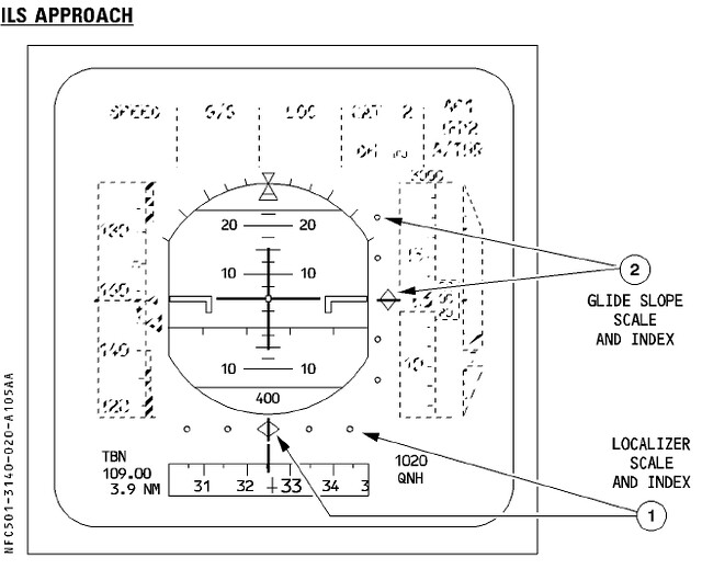
Let’s take a look at the ILS display on the PFD. Taking the Boeing 777 as an example,
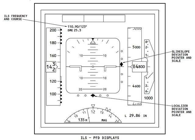 The diamond display on the right side of the central Attitude Indicator on the PFD shows the captured Glideslope position.
The display in the image above indicates that the aircraft’s current altitude is lower than the required Glideslope altitude, so the Rate of Descent should be moderately reduced to adjust the flight altitude.
The diamond below the Attitude Indicator shows the Localizer position; since it is in the center, it means the aircraft’s Track is aligned exactly with the Runway direction.
At the same time, you can see the ILS station information displayed in the upper left of the Attitude Indicator; the signal frequency, course, and distance are all clear at a glance.
The diamond display on the right side of the central Attitude Indicator on the PFD shows the captured Glideslope position.
The display in the image above indicates that the aircraft’s current altitude is lower than the required Glideslope altitude, so the Rate of Descent should be moderately reduced to adjust the flight altitude.
The diamond below the Attitude Indicator shows the Localizer position; since it is in the center, it means the aircraft’s Track is aligned exactly with the Runway direction.
At the same time, you can see the ILS station information displayed in the upper left of the Attitude Indicator; the signal frequency, course, and distance are all clear at a glance.
For comparison, let’s look at the ILS information display on the Airbus A320’s PFD,
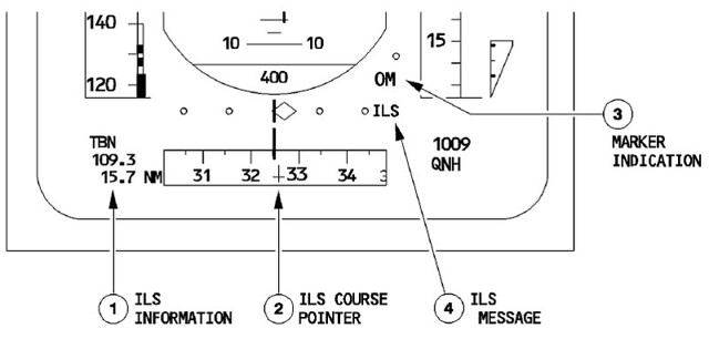 It can be seen that the displays on Airbus and Boeing aircraft are substantially the same,
The Glideslope to the right of the Attitude Indicator, the Localizer information below, and the ILS station information need no further explanation.
It can be seen that the displays on Airbus and Boeing aircraft are substantially the same,
The Glideslope to the right of the Attitude Indicator, the Localizer information below, and the ILS station information need no further explanation.
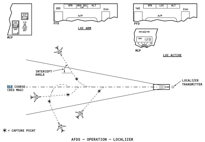
Alright, the series of operations up to this point can be summarized in the figure below, with data from the Airbus A320 series crew training manual.
 Engage APP mode, LOC and G/S modes are activated, and the second autopilot is engaged,
The LOC course intercepts and captures the signal, and then the G/S signal is also captured,
The aircraft is able to begin descending altitude under the guidance of the radio waves.
Engage APP mode, LOC and G/S modes are activated, and the second autopilot is engaged,
The LOC course intercepts and captures the signal, and then the G/S signal is also captured,
The aircraft is able to begin descending altitude under the guidance of the radio waves.
For the series of FMA status changes, let’s refer to the previous Boeing 737 Japanese data,
 During the Level Flight phase while flying through the FAF, operation #28 is to push the APP approach switch “Push APP”;
Start the second flight director/autopilot, “Push CMD B” is operation #29 in the diagram;
At item #30, the Localizer signal is captured, and the HDG SEL display disappears;
At item #31, the Glideslope signal is captured, and the ALT HOLD display disappears.
Looking at the image above, combined with the first image in this section, makes it easier to understand.
During the Level Flight phase while flying through the FAF, operation #28 is to push the APP approach switch “Push APP”;
Start the second flight director/autopilot, “Push CMD B” is operation #29 in the diagram;
At item #30, the Localizer signal is captured, and the HDG SEL display disappears;
At item #31, the Glideslope signal is captured, and the ALT HOLD display disappears.
Looking at the image above, combined with the first image in this section, makes it easier to understand.
End Prev: Landing Aid Systems TOC: Table of Contents Next: Traffic Pattern