Exploring Airliner Cockpits 6.2 Landing Assistance Systems
Landing aid systems include the so-called Blind Landing System, which is the Instrument Landing System (ILS), as well as the Precision Approach Path Indicator (PAPI). In addition, transmissometers used to measure Runway Visual Range (RVR) can often be seen near the airport Runway. From a personal experience perspective, when traveling to visit relatives or on business trips by air, being able to identify the various pieces of equipment at the airport greatly enhances the enjoyment of the journey.
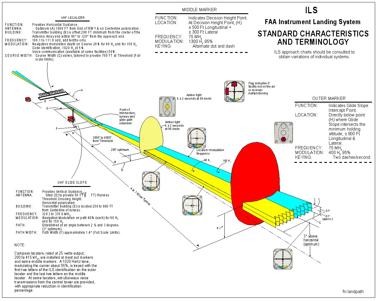
The Instrument Landing System (ILS) is currently the most widely used system for the precision approach and landing guidance of aircraft. Its function is to provide horizontal guidance via the Localizer and vertical guidance via the Glide Slope using radio signals transmitted from the ground, establishing a virtual path pointing from the Runway into the air. Through airborne receiving equipment, the aircraft determines its relative position to this path, allowing it to fly towards the Runway in the correct direction and descend steadily, ultimately achieving a safe landing. Because the Instrument Landing System can guide aircraft for approach and landing under low weather standards or when the pilot has no visual reference, it is commonly referred to as a Blind Landing system.
The specific locations of the Localizer and Glide Slope equipment within the airport can be found in the ILS system conceptual diagram below.
Let’s take a specific look at the Localizer and Glide Slope.
From the diagram above, it can be seen that two radio beams of equal intensity emitted by the Localizer ground antenna form a yellow and blue virtual path. (The VHF signal transmitted by the Localizer in the upper left uses 90Hz and 150Hz AM modulation frequencies respectively, which allows the area facing the Runway to be divided into left and right parts.) When facing the Runway on the approach direction, the yellow zone on the left is the 90Hz signal, and the blue zone on the right is the 150Hz signal. Therefore, the aircraft’s receiving equipment can determine the current position based on the difference in strength between the two signals, providing the pilot with information on whether they are aligned with the center of the Runway; if offset, the deviation is displayed so the pilot can adjust.
The horizontal guidance signal (LOC signal) emitted by the Localizer (LOC/LLZ) has a frequency between 108.8 and 111.95 MHz.
The beam is a very narrow sector, providing Heading (horizontal position) guidance relative to the Runway.
The Localizer antenna array is located at the far end of the approach direction, typically set about 300 meters from the Runway threshold.
Below is a photo I took at Hiroshima Airport.
 You can see that this Localizer consists of a set of red antennas and is located at the end of Runway 28;
therefore, it provides horizontal guidance for aircraft landing on Runway 10.
You can see that this Localizer consists of a set of red antennas and is located at the end of Runway 28;
therefore, it provides horizontal guidance for aircraft landing on Runway 10.
Here is another look at a Localizer antenna used for Runway 06R at Kansai International Airport.
 On that day, landings were using the reciprocal Runway 24L, and a JAL 737 is passing directly over the LOC.
The Glide Slope (GS or Glide Path, GP) provides Glide Slope (vertical position) guidance relative to the Runway threshold via a beam with an elevation angle of approximately 3 degrees. The Glide Slope is located 500 feet from the side of the Runway and 1000 feet from the approach end. It uses a frequency between 329.6 and 335.4 MHz, similar to the Localizer beam. The Glide Slope beacon beam is also composed of two beams of equal intensity, distributed above and below the 3º Glide Slope relative to the ground. Above the Glide Slope, the beam is modulated at 90Hz; below the Glide Slope, it is modulated at 150Hz. If the aircraft’s descent path is higher than the Glide Slope, the 90Hz signal is stronger, the instrument needle moves down, and the pilot lowers the aircraft’s nose; Conversely, if the 150Hz signal is stronger, the aircraft should Climb; When the two beam strengths are equal, the aircraft maintains the normal 3º descent path and lands smoothly on the Runway.
The Glide Slope antenna is somewhat simpler than the Localizer.
 The photo above was taken outside Runway 32L at Osaka International Airport (Itami).
You can see the red and white antenna standing in the center of the frame, which is the Glide Slope.
The photo above was taken outside Runway 32L at Osaka International Airport (Itami).
You can see the red and white antenna standing in the center of the frame, which is the Glide Slope.
Incidentally, on the right side of the photo above, there is also a red device, the RVR detector. This is not a navigation facility;
it is used to measure Runway Visual Range data.
Runway Visual Range (RVR) defines the distance over which a pilot in an aircraft on the Runway centerline can see the runway markings, Runway edge lights, or centerline lights.
The categories of the ILS system were introduced in Section 5.4 Instrument Approach Charts. For Category III C (CAT III C), which has the highest precision,
a safe landing is possible even when the Runway Visual Range is zero.
Let’s look at images of some aviation weather measurement equipment visible at the airport.
RVR Detector:
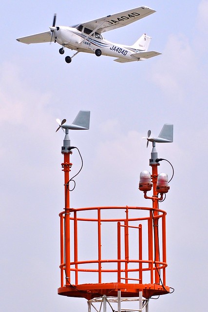
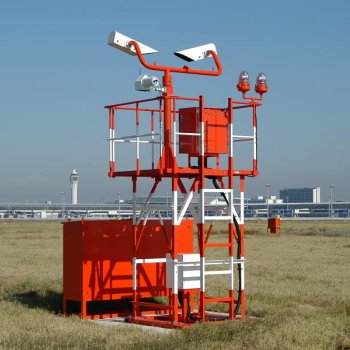 Anemometer (Wind Speed and Direction Indicator):

Additionally, there is a small antenna to the left of the Glide Slope antenna. This is the DME (Distance Measuring Equipment), which provides distance information to the Glide Slope for the aircraft.
Here is a close-up:
 The photo above was taken at Kansai International Airport.
The ILS system also includes Marker Beacon equipment. Combined with the system conceptual diagram above, you can see that from farthest to nearest the Runway, there are the Outer Marker, Middle Marker, and Inner Marker (not labeled in the diagram). These provide rough distance information relative to the Runway threshold, typically indicating that as the aircraft flies over these beacons in sequence, it reaches the Final Approach Fix (FAF), the Decision Height for Category I operations, and the Decision Height for Category II operations.
The Outer Marker is located 5 nautical miles from the Runway end. When an aircraft flies over it, a blue light flashes in the cockpit and a 400Hz audio signal sounds.

The Middle Marker is located 0.5 nautical miles (915 meters, 3000 feet) from the Runway end. When an aircraft flies over it, an amber light flashes
and a 1300Hz audio signal alerts the pilot to pay attention. At this point, the altitude is approximately 60m (200 feet).

The Inner Marker is located only 305m (1000 feet) from the Runway end. When an aircraft passes it, the altitude is only 30m (100 feet).
This is the Decision Height for Category II ILS operations. Upon passing, a white light flashes in the cockpit and a 3000Hz audio warning signal sounds.

The airport also provides PAPI, which is a visual reference system that provides visual reference for the aircraft’s position relative to the correct Glide Slope.
The full name of PAPI is Precision Approach Path Indicator,
and it is a type of Visual Approach Slope Indicator (VASI).
It consists of a set of lights installed next to the Runway, serving as a signal to the pilot indicating whether the approach angle is appropriate.
 PAPI is typically set at a distance of 110 to 175 meters from the Runway threshold, with each light spaced 10 meters apart, and the light nearest the Runway is 9 to 18 meters from the Runway.
 When the indicator lights show two reds and two whites (from left to right), it represents the correct altitude on approach, meaning the aircraft's Glide Slope angle is 3.0°.
If the indicator lights show one white and three reds, it means the aircraft's Glide Slope angle is 2.8°, slightly lower than the standard angle.
If the indicator lights show four reds, the aircraft's Glide Slope angle is below 2.5°, which is significantly lower than the standard Glide Slope angle.
Similarly to the four red signal, if the indicator lights are four whites, it means the aircraft's Glide Slope angle is above 3.5°, which is significantly higher than the standard Glide Slope angle.
When the indicator lights show two reds and two whites (from left to right), it represents the correct altitude on approach, meaning the aircraft's Glide Slope angle is 3.0°.
If the indicator lights show one white and three reds, it means the aircraft's Glide Slope angle is 2.8°, slightly lower than the standard angle.
If the indicator lights show four reds, the aircraft's Glide Slope angle is below 2.5°, which is significantly lower than the standard Glide Slope angle.
Similarly to the four red signal, if the indicator lights are four whites, it means the aircraft's Glide Slope angle is above 3.5°, which is significantly higher than the standard Glide Slope angle.
PAPI facilities can also be seen from the ground. Below are photos I took outside Runway 32L at Osaka International Airport (Itami).
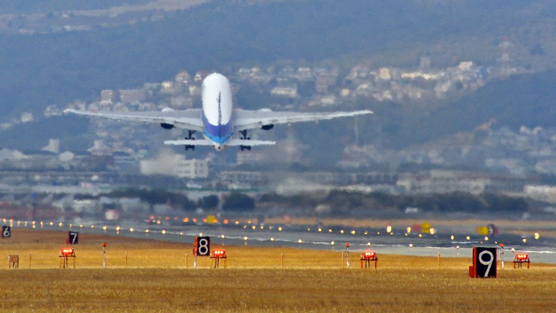
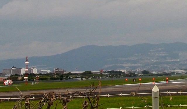 The Glide Slope is on the left side of the frame, and on the grass adjacent to the Runway on the right, you can see 4 red lights; this is the PAPI (front view).
Since this was taken from the ground, the angle is zero, so the four reds display is correct.
The Glide Slope is on the left side of the frame, and on the grass adjacent to the Runway on the right, you can see 4 red lights; this is the PAPI (front view).
Since this was taken from the ground, the angle is zero, so the four reds display is correct.
PAPI, Glide Slope, Windsock, RVR, and DME equipment can also be seen from the aircraft.
For example, in the photo below taken at Kansai International Airport, while the aircraft was taxiing on the ground and about to enter Runway 06R,
the four PAPI lights on the ground nearby (rear view) could be clearly seen from the cabin window, as well as the distant ILS Glide Slope and DME antennas.

End Prev: Control during Radar Vectoring Approach TOC: Table of Contents Next: Final Approach Fix and ILS Setup