Inside the Cockpit 2.1 5 Minutes Before Departure
While the pilot performs pre-flight preparations inside the cockpit, the ground crew is also busy preparing for the flight.
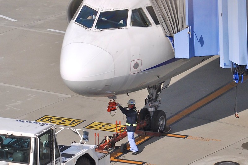
For example, they disconnect the power supply cable, ensure catering trucks, fuel trucks, and cargo dollies are moved away from the aircraft, and connect the tow tractor to the nose landing gear.
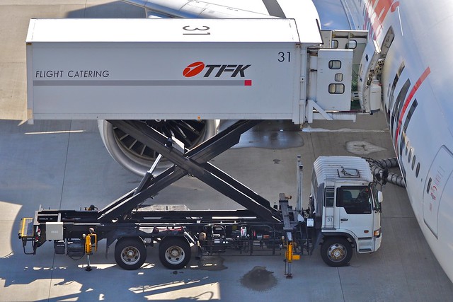 Catering truck, photographed by me at Tokyo International Airport.

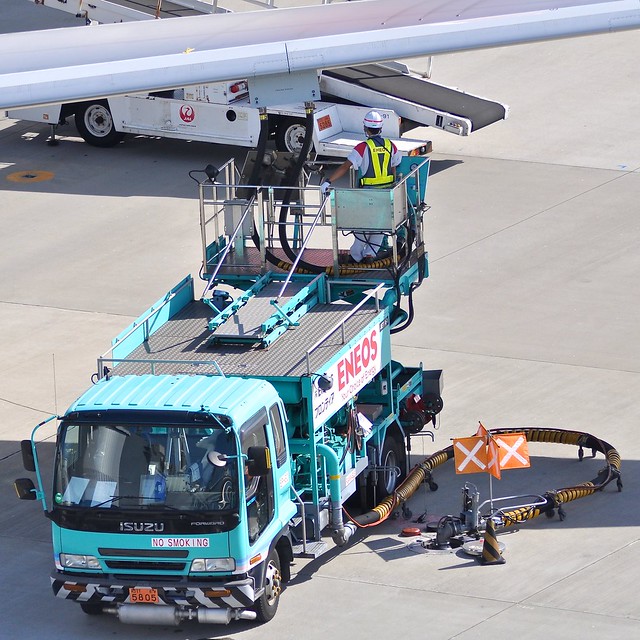 Fuel truck, photographed at Tokyo International Airport.
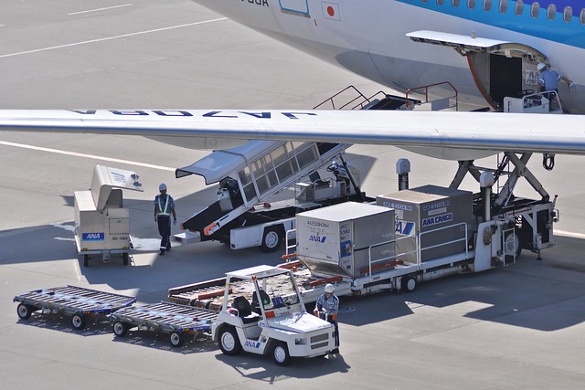 Cargo dolly, photographed at Tokyo International Airport.
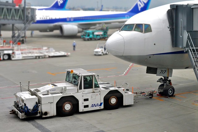 Tow tractor, photographed at Tokyo International Airport.
 Ground crew disconnecting the ground power cable from a Boeing 777, photographed at Hiroshima Airport.
Once all vehicles and equipment that could obstruct movement are removed from the vicinity of the aircraft, the ground preparation is complete.
Ground mechanics notify the pilot via the hard-wired interphone that it is 5 minutes until departure.
 (Photo taken at Nagoya Chubu Centrair International Airport)
The Captain then instructs the First Officer to contact ATC via radio to request clearance.
Generally, large airports have dedicated frequencies for delivery clearance. Smaller airports, with less traffic, handle clearance requests directly through the Tower.
In the Pre-flight Briefing section, it was mentioned that the dispatcher submits the flight plan to the government agency responsible for managing all flights—the Civil Aviation Bureau. This flight plan has now been transmitted to the airport controllers. Only after the pilot completes all pre-flight preparations (5 minutes before departure) can they formally request clearance from ATC. Without ATC clearance, the aircraft cannot start engines, leave the gate, or taxi to the Runway.
At this point, the First Officer tunes the VHF radio to the Delivery frequency and makes the request via the microphone. Taking Air System 115 flight from Haneda to Hokkaido as an example:
Pilot: “Tokyo Delivery, Air System 115, Gate 2” (Meaning: “Tokyo Haneda Delivery, this is Air System 115, at Gate 2”)
Upon receiving this radio request, the Airport Delivery Controller replies:
Controller: “Air System 115, Tokyo Delivery, Cleared To New Chitose Airport, Moriya 7 Departure flight plan route, maintain flight level 210, Squawk 2460, Readback only Squawk” (Meaning: “Air System 115, cleared to New Chitose Airport via the Moriya 7 Departure. Maintain Flight Level 210. Squawk 2460. Read back only the Squawk code.”)
The pilot then reads back:
Pilot: “Squawk 2460, Air System 115” (Meaning: “Squawk 2460, Air System 115”)
The Delivery Controller then informs the pilot of the Ground Control frequency to be used during pushback and taxiing:
Controller: “Air System 115, monitor Ground 121.7, advise when ready for pushback” (Meaning: “Air System 115, monitor Ground Control on 121.7. Advise when ready for pushback.”)
The pilot will briefly read back “121.7” and tune the radio frequency to 121.7 MHz.
As you can see, Air Traffic Control dialogues follow a specific set of phraseology. Without specialized training, it is very difficult for the average person to understand. Due to space limitations, I won’t explain every specific term here.
For important information during the communication, pilots must read back the instructions they receive. This is because the transmission is via radio; if there is signal interference or if the pilot mishears, a safety accident could occur. The controller verifies the pilot’s readback and corrects it immediately if there is an error.
The dialogue above mentioned the Squawk code. The Transponder is an electronic device that transmits aircraft information to ATC radar via radio waves. This allows the controller to see more than just a blip on the radar screen; they can see the flight number, altitude, speed, and other details, making it easier to distinguish each flight.
If the Departure procedure given by ATC differs from the pre-set one, the pilot must input the new settings into the FMS and re-check the route displayed on the MFD.
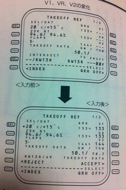
At this time, data regarding aircraft weight, center of gravity, passenger count, etc., is also transmitted to the cockpit via the ACARS (Aircraft Communications Addressing and Reporting System). The pilot inputs this information into the FMS. For specific methods, refer to Cockpit Preparation and FMS CDU Setup Guide. This generates critical takeoff data such as Decision Speed V1, Rotate Speed Vr, and Safety Takeoff Speed V2, as well as roll distance. The pilot then sets the takeoff Flaps, engine Thrust, horizontal stabilizer Trim, etc.
Before V1, Vr, and V2 are confirmed, they are displayed in small font. Once confirmed using the 1R, 2R, and 3R keys, they change to large font, as shown below:
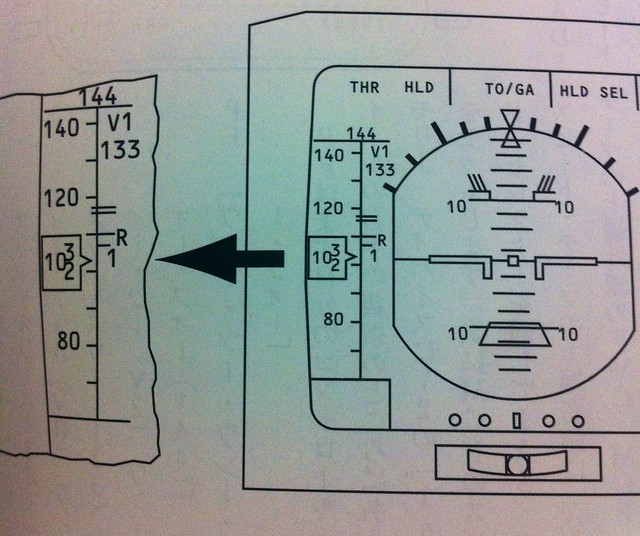
 They are also displayed on the ND (Navigation Display), as shown below:
Finally, the Captain and First Officer complete the items below the dotted line on the cockpit checklist together.
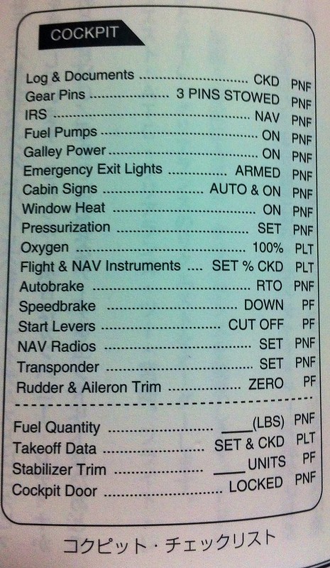
Since the aircraft is about to taxi on the ground, the anti-collision light switch must be turned on to prevent accidents.
The Captain will ask the First Officer to turn on the hydraulic pump switches so that fuel can be transferred to the engines, ensuring a normal and safe engine start.
Meanwhile, the cabin crew closes the cabin doors and reports to the Captain. The Captain can see the status of all doors on the EICAS. Once confirmed that the cargo doors are also secured,
 the aircraft is finally ready to leave the gate.
Air Traffic Control uses the VHF (Very High Frequency) band to communicate with ground control stations. This band ranges from 118 to 135.975 MHz and is standardized worldwide. Each airport uses specific frequencies for Delivery Clearance, Ground movement, Tower takeoff and landing management, etc. These frequencies can be found for free online. If you have a radio or wireless receiver capable of receiving aviation bands, try listening to the actual dialogue between pilots and controllers. The immersion won’t disappoint you. In the following sections, I will continue to introduce ATC communication content during various flight phases.
A diagram of the Radio Control system used by pilots is shown below. It is located on the lower sides of the CDU, beneath the engine throttle.
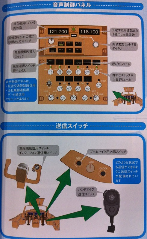 The aircraft is equipped with multiple radios. Each radio has Active and Standby frequencies. To tune, first input the desired frequency into the Standby window, then use the ← → key in the middle to activate it. The previous Active frequency then swaps into the Standby window.
Additionally, the lower part of the image above introduces the transmit buttons. You can see there are multiple buttons available in the cockpit: on the control yoke, the front panel, and the black handheld switch below. This allows pilots to use the closest button during busy operations, greatly improving convenience.
The image below shows the locations of various radio communication antennas on a Boeing 747-400. Besides those mentioned for control and navigation, there are many other antennas for different purposes, which I will introduce slowly in the future.

Prev: Pre-flight Procedures and Cockpit Interior TOC: Table of Contents Next: Standard Instrument Departure SID End