Title: Exploring the Cockpit 1.6 Cockpit Preparation
While the Captain performs the exterior inspection on the ground, the First Officer is certainly not idle; they must complete the pre-flight preparation procedures and the CDU pre-flight procedures. Let me briefly introduce these tasks.
First, the First Officer must check various documents in the cockpit. Just like a car needs an annual inspection certificate, an aircraft needs an airworthiness certificate; an aircraft without an airworthiness certificate cannot fly. The flight log and maintenance documents record all flight and maintenance history of the aircraft, and these documents must not be missing.
Then, the fuel quantity determined during the flight preparation meeting needs to be verified as loaded.
Additionally, various emergency equipment items are checked, such as fire extinguishers, signal flares, flashlights, emergency axes, escape ropes, life vests, asbestos gloves, and smoke hoods.
The emergency axe can be used to break open windows. The escape rope is a rope attached to the cabin ceiling; in the event of a crash landing or other emergency where evacuation through the door is impossible, the emergency escape hatch in the ceiling can be opened, the rope thrown out the window, and then one climbs out the window and descends using the rope.
 The image above shows the emergency evacuation procedures for the cockpit side window emergency exit on a Boeing 737.
There are also test switches to check for normal operation, and some initial settings such as landing gear down, flap position readiness, engine oil quantity, oxygen pressure, and so on. It’s a long list, too tedious to enumerate here one by one.
As we all know, modern airliners feature automatic flight management functions; from takeoff Climb to cruise Descent and finally landing, it can all be controlled automatically by computer. Flight attitude control is handled by the Inertial Navigation System. Since the system relies on internal reference, pilots need to align the aircraft’s internal IRS (Inertial Reference System) before takeoff to make navigation more precise. Regarding how inertial navigation relies on gyroscopes and accelerometers, I will explain these principles separately in the future if there is an opportunity.
Alignment settings need to be entered via the FMS’s CDU. So, what are the FMS and CDU?
FMS stands for Flight Management System, a navigation/guidance and performance management system centered around the Flight Management Computer. If the engine is the heart of the aircraft, then the FMS is the brain. The IRS mentioned above is also part of the FMS, providing position information to the computer. The CDU (Control Display Unit) allows pilots to input various information required for flight, such as weight and route. The computer then automatically calculates takeoff speeds, economy speeds, cruise altitude, and engine Thrust, sending various control commands to the autopilot and autothrottle systems to complete automatic flight control. For example, after engaging the auto mode, the throttles and control column of a Boeing aircraft move automatically forward, backward, left, and right, just like an invisible hand is manipulating them. The FMS greatly reduces the pilot’s operational burden, allowing them to free up more time to monitor various internal systems, listen to Air Traffic Control, observe air traffic and weather conditions, and greatly improving flight safety.
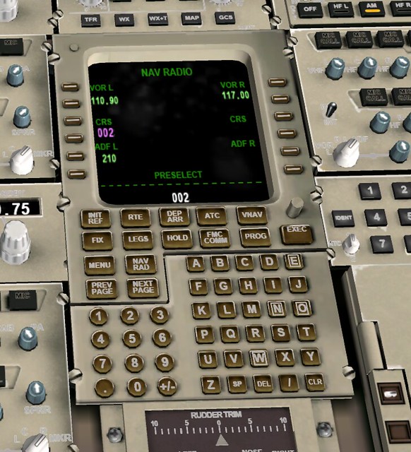
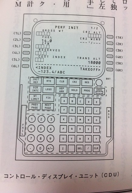 As shown in the figure above, the CDU consists of a screen, six keys on the left and right sides of the screen, and function keys and an alphanumeric keyboard below.
The keys on the left side of the screen, from top to bottom, are called 1L, 2L, 3L, 4L, 5L, 6L.
Similarly, the keys on the right are called 1R, 2R, 3R, 4R, 5R, 6R.
Each key corresponds to an input item or command; pressing the key is equivalent to selecting and executing that command, or acting as the Enter key after using the alphanumeric keys.
As shown in the figure above, the CDU consists of a screen, six keys on the left and right sides of the screen, and function keys and an alphanumeric keyboard below.
The keys on the left side of the screen, from top to bottom, are called 1L, 2L, 3L, 4L, 5L, 6L.
Similarly, the keys on the right are called 1R, 2R, 3R, 4R, 5R, 6R.
Each key corresponds to an input item or command; pressing the key is equivalent to selecting and executing that command, or acting as the Enter key after using the alphanumeric keys.
Initial data entry on the CDU includes the aircraft model, navigation database, system time confirmation, and then entering the latitude and longitude of the current parking position to complete the inertial navigation system alignment.
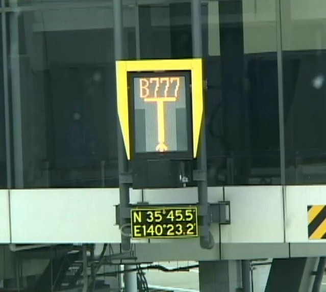
Generally speaking, there is a signboard directly in front of the cockpit at the parking gate displaying the latitude and longitude of the location. The pilot can see this data simply by looking up. The image below shows the display at a certain Gate at Narita Airport.
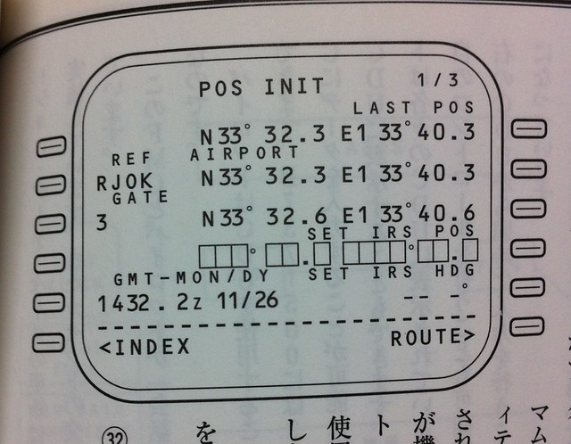
An example of CDU input is shown below. The current airport RJOK Kochi Airport, Japan (2L), Gate 3 (3L), current time (5L), airport latitude/longitude (2R), and Gate 3 latitude/longitude (3R) have been entered:
 Next comes the flight navigation data, such as flight number, airports, route, Runway, etc.
In the performance input, data such as Zero Fuel Weight, fuel quantity, engine N1 limits, and center of gravity are required. The computer then calculates several important speed data needed for takeoff: V1, Vr, and V2.
Next comes the flight navigation data, such as flight number, airports, route, Runway, etc.
In the performance input, data such as Zero Fuel Weight, fuel quantity, engine N1 limits, and center of gravity are required. The computer then calculates several important speed data needed for takeoff: V1, Vr, and V2.
V1 is called the takeoff decision speed. During takeoff, while accelerating to V1, if the Captain feels any abnormality, such as engine failure or insufficient RPM, takeoff should be aborted, because decelerating the aircraft before V1 speed allows it to be stopped on the existing Runway. However, if the indicated airspeed has exceeded V1, then given the existing Runway length, there is not enough Runway left to stop the aircraft. Therefore, regardless of the situation, takeoff must be continued, and checks and countermeasures considered only after getting airborne.
Vr is the rotation speed. Before this speed, the aircraft remains in the ground taxiing state; once reaching Vr, the Captain pulls the control column, causing the nose to pitch up, maintaining a pitch attitude of 10-15 degrees to lift off.
V2 is the takeoff safety speed. After the aircraft leaves the ground, the pitch attitude is adjusted appropriately to accelerate to V2 as quickly as possible, and then continue accelerating to the standard Climb speed.
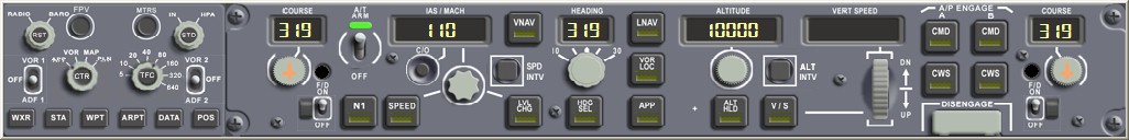
Regarding the MCP (Mode Control Panel), the COURSE number for the Standard Instrument Departure procedure should be set in advance. Set Autothrottle and Flight Director (FD) to OFF, set Airspeed (IAS/MACH), set Heading (HEADING) to the Runway direction, set Altitude (ALTITUDE) to the altitude in the flight plan, etc.
At this point, the cockpit preparation procedures are basically ready, and the Captain and First Officer can begin the Before Start procedure (to officially bring the aircraft to flight status).
Prev: 1.5 航行前地面检查 TOC: 目录 Next: 1.7 CDU设置详解
完