Title: Uncovering the mysteries of airliner piloting 1.7 FMS CDU setup detailed explanation
Considering that flight simulation enthusiasts are likely interested in the detailed settings of the Flight Management System Control Display Unit (FMS/CDU), I have dedicated a specific section to introduce the initial setup of the CDU.
The CDU is the device used by pilots to input flight data. It looks like a large calculator, consisting of a square display and an alphanumeric keyboard. Modern airliner cockpits are generally equipped with 3 CDUs, located between the Captain and the First Officer seats, as shown in the 747-400 cockpit below:

Although the material below is quite old, derived from the Boeing 737-500 introduction in the book 旅客機操縦マニュアル (Airliner Operation Manual) published in 1998, the general content is not significantly different from modern new aircraft, so I believe it is still quite relevant. For figures not included in this book, I have directly linked images from http://www.b737.org.uk/fmc.htm here for easier understanding.
First, after the power is turned on, the CDU automatically starts up at the Position Initialization page “POSITION INIT”. In the previous section, I have already introduced the method for inputting latitude/longitude and using function keys. If you have forgotten, please review it.

Press the 6L key to return to the Index page, and the display shows the Initialization/Reference Index page “INIT/REF INDEX 1/1”.

Press the 1L key to enter the following Aircraft Identification Page “IDENT” (identification),
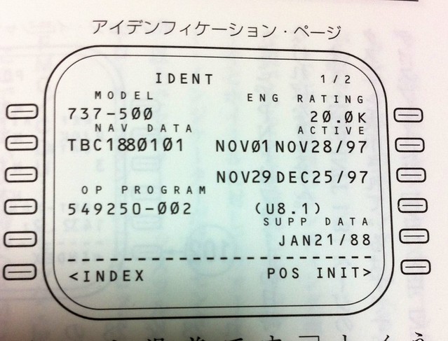 Here, check if the aircraft model is correct and if the navigation database data in the FMC is the latest. For example, if the data in the “active” (2R) section is older than the 3R section, press the 3R key to activate the latest data.
As explained in the Airliner Operation Manual, the navigation database is the responsibility of ground staff and is updated every 28 days.
Therefore, you can see that the validity periods for the 2R and 3R data in the figure above are also exactly 28 days.
Here, check if the aircraft model is correct and if the navigation database data in the FMC is the latest. For example, if the data in the “active” (2R) section is older than the 3R section, press the 3R key to activate the latest data.
As explained in the Airliner Operation Manual, the navigation database is the responsibility of ground staff and is updated every 28 days.
Therefore, you can see that the validity periods for the 2R and 3R data in the figure above are also exactly 28 days.
The next step is to press the RTE function key (I couldn’t find a 737-500 CPU image, so I had to use the 747-400 as a substitute again),
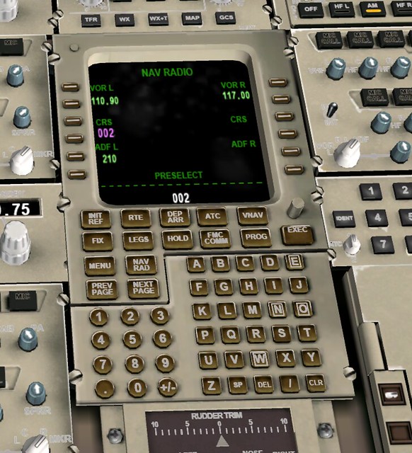 to enter the Route setup page “RTE”.
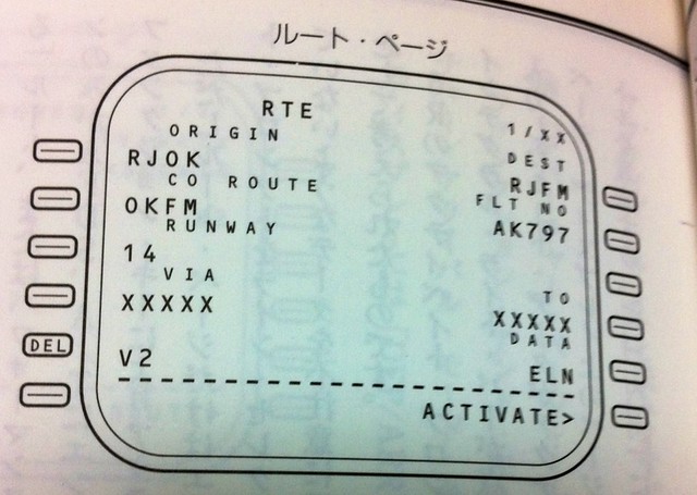 Input the origin airport code RJOK (Kochi Airport) into 1L, and the destination airport code RJFM (Miyazaki Airport) into 1R.
The meaning of “CO ROUTE” in 2L is the company route number; this data is already stored in the database, and the pilot only needs to simply input the code “OKFM” here.
Next, input the takeoff Runway 14 information into 3L, and the flight number AK797 into 2R.
Since the specific waypoints are the airline’s internal confidential information, they are not displayed in the figure above.
Navigation waypoints such as VOR/NDB/ILS/FIX along the route are displayed here in sequence,
as shown below:
Input the origin airport code RJOK (Kochi Airport) into 1L, and the destination airport code RJFM (Miyazaki Airport) into 1R.
The meaning of “CO ROUTE” in 2L is the company route number; this data is already stored in the database, and the pilot only needs to simply input the code “OKFM” here.
Next, input the takeoff Runway 14 information into 3L, and the flight number AK797 into 2R.
Since the specific waypoints are the airline’s internal confidential information, they are not displayed in the figure above.
Navigation waypoints such as VOR/NDB/ILS/FIX along the route are displayed here in sequence,
as shown below:

 The “VIA” and “TO” on each line represent a flight segment, corresponding to the Navigation Log during the flight preparation briefing.
Pilots use this page to check if there are any errors in the waypoint information. If there are no issues, press the 6R “ACTIVATE” key to activate the route.
At this point, the “EXEC” function key will light up. Pressing EXEC completes the route setup, and the page display changes from RTE to ACT RTE (Active Route?).
This allows the flight computer to control LNAV (Lateral Navigation), RNAV (Area Navigation/Vertical Navigation), and A/T (Autothrottle).
The “VIA” and “TO” on each line represent a flight segment, corresponding to the Navigation Log during the flight preparation briefing.
Pilots use this page to check if there are any errors in the waypoint information. If there are no issues, press the 6R “ACTIVATE” key to activate the route.
At this point, the “EXEC” function key will light up. Pressing EXEC completes the route setup, and the page display changes from RTE to ACT RTE (Active Route?).
This allows the flight computer to control LNAV (Lateral Navigation), RNAV (Area Navigation/Vertical Navigation), and A/T (Autothrottle).
The next step is to input Departure settings. After pressing the DEP/APR (Departure/Arrival) function key, the DEP ARR INDEX screen is displayed,
 Press 1L again to enter the Kochi Airport Departure Procedures “RJOK DEPARTURES” screen:
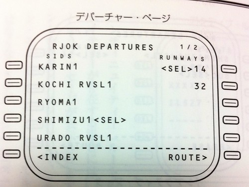
The Kochi Airport Departure screen first displays a list of SID (Standard Instrument Departure) procedures and RUNWAYs. These are preset in the navigation data.
The pilot only needs to select the settings that have already been decided. In the figure above, you can see that the “SHIMIZU1” SID procedure at 4L and Runway 14 at 1R are selected.
The  “TRANS” is the en route waypoint SUC, located between Kochi and Miyazaki airports.
At this point, the EXEC key lights up again. After pressing EXEC to execute, the CDU display changes to the lower part of the figure above.
The part that was
“TRANS” is the en route waypoint SUC, located between Kochi and Miyazaki airports.
At this point, the EXEC key lights up again. After pressing EXEC to execute, the CDU display changes to the lower part of the figure above.
The part that was
The next step is to check if the points on the route are correctly connected.
Press the LEGS function key to bring up the ACT RTE LEGS screen, and use the PREV PAGE and NEXT PAGE keys to flip back and forth.
If there is a discontinuity anywhere, it will appear as shown below
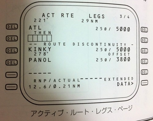 A box is displayed at the discontinuity, and the error message “ROUTE DISCONTINUITY” appears.
The pilot can simply select the waypoint below the error message to connect them.
Additionally, after modification, the screen display changes from ACT RTE LEGS to MOD RTE LEGS, and the EXEC key lights up again. Press it to complete the setup.
A box is displayed at the discontinuity, and the error message “ROUTE DISCONTINUITY” appears.
The pilot can simply select the waypoint below the error message to connect them.
Additionally, after modification, the screen display changes from ACT RTE LEGS to MOD RTE LEGS, and the EXEC key lights up again. Press it to complete the setup.
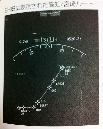
The route can also be displayed in the PLAN mode on the ND (Navigation Display), as shown below.
Next, we will do the performance settings. Don’t forget that the FMC also has a powerful performance database to ensure the aircraft achieves good fuel economy under any conditions.
Press the INIT/REF function key to enter the PERF INIT (Performance Initialization) screen.
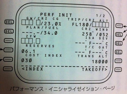 First, look at the “COST INDEX” item at 5L. The larger this value is, the more the Flight Management Computer prioritizes speed over fuel consumption.
The smaller this value is, the more the computer prioritizes fuel consumption. It is said that the default value of 30 is generally used.
The next value is “RESERVES” at 4L, which is the reserve fuel amount.
There is also the cruise altitude setting at 1R, which is 18000 feet this time, and wind direction/speed set at 2R.
“ISA DDEV” at 3R is the pressure and temperature setting for the International Standard Atmosphere deviation at the cruise altitude; generally, in clear weather, there is no need for specific settings.
First, look at the “COST INDEX” item at 5L. The larger this value is, the more the Flight Management Computer prioritizes speed over fuel consumption.
The smaller this value is, the more the computer prioritizes fuel consumption. It is said that the default value of 30 is generally used.
The next value is “RESERVES” at 4L, which is the reserve fuel amount.
There is also the cruise altitude setting at 1R, which is 18000 feet this time, and wind direction/speed set at 2R.
“ISA DDEV” at 3R is the pressure and temperature setting for the International Standard Atmosphere deviation at the cruise altitude; generally, in clear weather, there is no need for specific settings.
Next, set the takeoff reference values. Press the 6R “TAKEOFF” item, and the TAKEOFF REF 1/2 page is displayed.
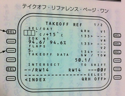 1L “OAT” is the Outside Air Temperature at the local takeoff airport; here, positive 15 degrees is entered.
“SEL” is the assumed temperature input to perform a reduced thrust takeoff, usually higher than the normal temperature, to reduce the risk of engine exhaust gas temperature (EGT) overheating.
At 3L, set the Flaps to 5 degrees for takeoff, then press the NEXT PAGE key to turn to the TAKEOFF REF 2/2 page.
1L “OAT” is the Outside Air Temperature at the local takeoff airport; here, positive 15 degrees is entered.
“SEL” is the assumed temperature input to perform a reduced thrust takeoff, usually higher than the normal temperature, to reduce the risk of engine exhaust gas temperature (EGT) overheating.
At 3L, set the Flaps to 5 degrees for takeoff, then press the NEXT PAGE key to turn to the TAKEOFF REF 2/2 page.
 1L is the runway wind direction and speed. The dispatcher has already prepared this data during the flight preparation briefing: 150 degrees at 8 knots.
Before takeoff, you can also listen to ATIS to get the latest information. Additionally, the Tower controller will provide this information again when issuing the “cleared for takeoff” instruction, and the pilot will update this data to the latest.
For an introduction to airport ATIS, you can refer to this site’s article Introduction to ATIS Automatic Terminal Information Service.
2L is the runway slope and alignment information. Kochi Airport is 0.2% slope and 137 degrees alignment.
5L is the reduced thrust takeoff setting. While the engine RATING was set to 20K on the IDENT page, it is now derated to 18.5K.
1L is the runway wind direction and speed. The dispatcher has already prepared this data during the flight preparation briefing: 150 degrees at 8 knots.
Before takeoff, you can also listen to ATIS to get the latest information. Additionally, the Tower controller will provide this information again when issuing the “cleared for takeoff” instruction, and the pilot will update this data to the latest.
For an introduction to airport ATIS, you can refer to this site’s article Introduction to ATIS Automatic Terminal Information Service.
2L is the runway slope and alignment information. Kochi Airport is 0.2% slope and 137 degrees alignment.
5L is the reduced thrust takeoff setting. While the engine RATING was set to 20K on the IDENT page, it is now derated to 18.5K.
When the passenger load is light, using reduced thrust for takeoff at a lower takeoff gross weight not only does not affect normal takeoff, but also increases safety and economic benefits, reduces engine wear, and reduces ground crew maintenance costs. It serves multiple purposes.
Finally, there is the N1 setting. Press the N1/LIMIT function key to enter the N1 LIMIT screen.
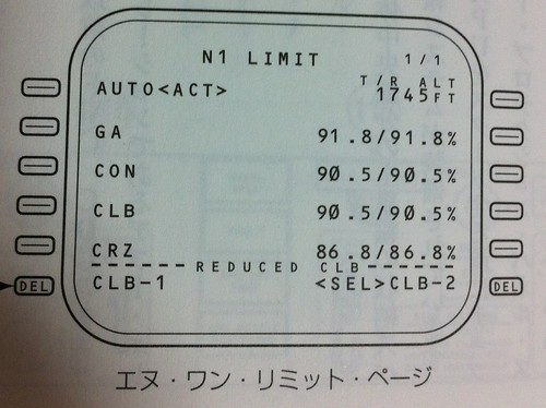 N1 is the percentage of the low-pressure rotor fan speed relative to its rated speed, so looking at the N1 value gives an intuitive understanding of the engine’s current thrust information.
On this N1 limit setting screen, the main task is to select the value for reduced thrust Climb, using 6L or 6R to make the selection.
N1 is the percentage of the low-pressure rotor fan speed relative to its rated speed, so looking at the N1 value gives an intuitive understanding of the engine’s current thrust information.
On this N1 limit setting screen, the main task is to select the value for reduced thrust Climb, using 6L or 6R to make the selection.
Alright, the basic CDU setup ends here.
Prev: 1.6 Cockpit Preparation Work TOC: Table of Contents Next: 1.8 Preflight Procedures and Cockpit Interior
End
Later, I found a nice webpage, 【Mariano出品】波音737NG开车及起飞爬升基本程序, which introduces the steps for operating the 737 in flight simulation software in great detail and is worth referencing.