A Flight Sim Enthusiast's Notebook
-
Observing Airliner Crosswind Takeoff
I recently visited Osaka International Airport again to observe aircraft takeoffs and landings at the approach end of Runway 32L. The set of photos below captures a sequence of a Boeing 777 jet airliner taking off in a left crosswind. This might be helpful for understanding aircraft control, so here is a brief summary.
Generally, after starting the takeoff roll, pilots use the cross-control technique (sideslip method): apply light left rudder, and point the nose slightly into the wind (to the right) to counteract the left crosswind’s weathercock effect; simultaneously, the left crosswind creates uneven Lift on the wings—greater on the left, less on the right. To maintain balance, the pilot applies left aileron input to decrease the Lift on the left wing. Consequently, the Lift on both wings is roughly equal, the aircraft remains in a basically balanced and stable state, and the nose points essentially toward the center of the Runway.
-
Secrets of Airliner Flying 6.3 Final Approach Fix and ILS Setup
In Section 6.1, we covered the aircraft passing the Intermediate Fix (IF) and entering a state of Level Flight. In this section, we will discuss the operations during the flight from the IF to the Final Approach Fix (FAF). The relationship between the IF and FAF was introduced in Section 5.4; let’s review that here.
On the NAV/RAD page of the CDU, verify that the entered data is correct, for example, check the landing Runway azimuth is 128 degrees and the radio frequency is 110.90MHz. The image below shows a schematic of the Boeing 777 CDU display.

-
Exploring Airliner Cockpits 6.2 Landing Assistance Systems
Landing aid systems include the so-called Blind Landing System, which is the Instrument Landing System (ILS), as well as the Precision Approach Path Indicator (PAPI). In addition, transmissometers used to measure Runway Visual Range (RVR) can often be seen near the airport Runway. From a personal experience perspective, when traveling to visit relatives or on business trips by air, being able to identify the various pieces of equipment at the airport greatly enhances the enjoyment of the journey.
-
x-plane 10 Small Aircraft VOR and NDB Instrument Navigation Introduction
X-Plane 11 is now available! Please check out the latest article: Installing and Trying the X-Plane 11 Free Demo!
Let’s take the Cessna 172 as an example to introduce how to use VOR and NDB navigation in X-Plane.
First, let’s look at the relatively simple NDB and ADF. The ADF (Automatic Direction Finder) equipped on the aircraft is a simple navigation device. It indicates the direction of the ground-based NDB (Non-Directional Beacon) station. An NDB is a simple radio transmitter. Since the NDB signal contains bearing data, the ADF automatically finds the direction and displays the Heading from the nose of the aircraft to the NDB station on the instrument.
-
Unveiling Airliner Flying 6.1 Control During Radar-Guided Approach
Section 5.6 summarized the dialogue during radar vectoring performed by Air Traffic Control. Below is a summary of the pilot’s specific operations during the arrival and approach phases.
When ATC issues a heading instruction, such as “Air System 115, Turn Left Heading 040”, it requires the aircraft to turn left to a heading of 040.
The pilot adjusts the HEADING knob on the Mode Control Panel (MCP) (refer to the Boeing 737 MCP diagram below),
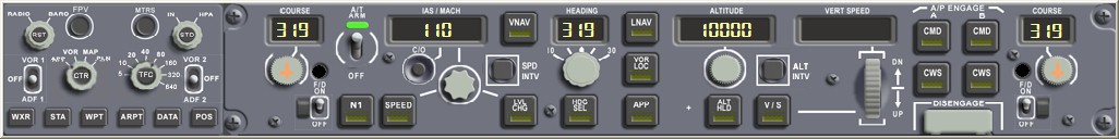 dialing the data in the display to 040. Then, the pilot presses the HDG SEL button below the knob.
At this point, the Flight Mode Annunciation (FMA) mode on the Flight Management System will change from Lateral Navigation (LNAV) to Heading Select (HDG SEL) mode.
dialing the data in the display to 040. Then, the pilot presses the HDG SEL button below the knob.
At this point, the Flight Mode Annunciation (FMA) mode on the Flight Management System will change from Lateral Navigation (LNAV) to Heading Select (HDG SEL) mode. -
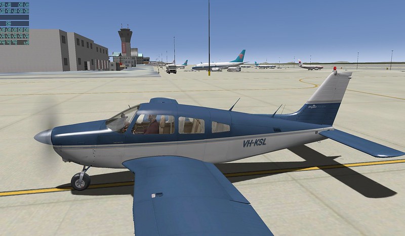
PA28 181 ARCHER II 2.0
I bought the PA28 181 ARCHER II during Carenado’s Christmas sale last year, and the 2.0 version was released yesterday. I upgraded immediately this morning and found that the new version is well-optimized for X-Plane 10. Therefore, it runs much more smoothly than previous versions; I guess I certainly won’t be using version 1.0 anymore.
Additionally, the 2.0 update includes significant sound improvements. At different throttle positions, the changes in engine sound are clearly audible. At the same time, the sound effects for opening/closing doors, tires touching down, and retracting/extending Flaps feel more realistic than before, significantly enhancing the overall immersion.
-
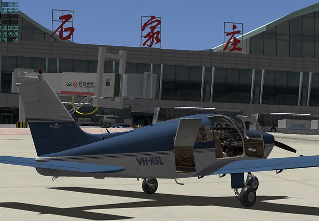
ZBSJ Shijiazhuang Zhengding International Airport Scenery for X-Plane 10.20
Here is the translation following your constraints: 常犯井的三胖 on Weibo, also known as ShaneMontoya on x-plane.org, has once again brought us a new surprise. This time, it is scenery for Shijiazhuang Zhengding International Airport. I immediately installed and gave it a try. I am very satisfied. Here is a quick introduction to everyone, with a few screenshots for the record.
This airport isn’t very large. Before departure, I boarded right in front of the terminal and loaded my luggage.
 Then I took a walk around the area,
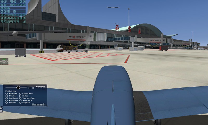 There are quite a few A320s and 737s from China Eastern and China Southern,
 Oh, there is also a cargo office here.

-
X-Plane Multi-Monitor Display Configuration Guide
X-Plane natively supports multi-screen display functionality. If you could have four monitors displaying the left, center, and right cockpit windows respectively, and dedicate a fifth monitor specifically for instruments, it would greatly enhance the fun of flight simulation. Unfortunately, I don’t have that many monitors; mainly, even if I could afford them, I have no place to put them. Also, driving 4 monitors with a single computer requires a very powerful hardware environment. Since iMacs do not support expandable graphics cards, the frame rate wouldn’t be smooth even with multiple screens. Therefore, here is a guide on setting up Multi-Monitor Display using Multiple Computers.
-
Checking Track Using Map
Spring is a season suitable for travel, with the side effect being that this blog has been neglected for a while. My apologies. I definitely must finish the “Airliner Cockpit Exploration” series by mid-May. (The photos I took in Kyoto, Nara, Fukushima, Tokyo, Nagano, etc., turned out to be quite a substantial harvest.)
Today, I flew for about an hour or so, practicing spiral high-speed Descents and ILS approaches. After finishing, I checked my Track in map mode. I felt the flight went pretty well, so I took a screenshot as a souvenir.
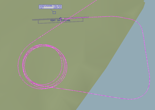 The image above shows the Track during the spiral Descent. I maintained a 30-degree bank angle while spiraling down at high speed from over 10,000 feet,
then leveled off at 1,000 feet to enter the Downwind, Base, and finally Final for landing.
Looking at the spiral, the circles I drew were fairly regular, giving me a small sense of accomplishment.
The image above shows the Track during the spiral Descent. I maintained a 30-degree bank angle while spiraling down at high speed from over 10,000 feet,
then leveled off at 1,000 feet to enter the Downwind, Base, and finally Final for landing.
Looking at the spiral, the circles I drew were fairly regular, giving me a small sense of accomplishment. -
X-Plane 10.21 Release Candidate 1
I saw some good news at noon: the latest version, 10.21 RC1, has finally been released, fixing the issue where the game failed to launch on Mac under Japanese and other locales.
I hurried to upgrade when I got home in the evening, and sure enough, this major bug that had plagued me for over half a year has finally been fixed. Kudos to the developers for their hard work.
-
Honolulu Intl Airport Scenery USA_HI_PHNL v 2.1
I recently found another free scenery package for Honolulu International Airport, created by the famous Freddy.
I recommend it because it features extensive details for the airport Runway and buildings. It includes not only the main terminal but also the Apron used by FedEx and other express companies on the south side, significantly enhancing the realism of the flight. Even more impressive is the inclusion of the US Air Force section; you can see military aircraft and hangars such as F15s, C17s, and DC10s, which is quite a bonus.
-
Various Altitudes: MEA MOCA MORA MAA MCA MRA
Source: Jeppesen Chart Tutorial MEA Minimum Enroute Altitude The minimum altitude between radio fixes, usually plotted above or below the route box, such as "←10000 8000→", "←6500", "→9900"; arrows indicate the direction of flight. MOCA Minimum Obstruction Clearance Altitude The published effective minimum obstacle clearance altitude between radio fixes, indicated by altitude and the suffix "T", such as 1300T. Enroute MORA Enroute Minimum Off Route Altitude Provides obstacle clearance clearance within 10 nautical miles of the route centerline and fixes, indicated by altitude and the suffix "a", such as 1300a. MAA Maximum Authorized Altitude The highest usable altitude or flight level published for a airspace or route segment (due to technical limitations, ground-based navigation equipment limitations, etc.), indicated by altitude and the prefix "MAA", such as MAA 25000 or MAA FL240. MCA Minimum Crossing Altitude The minimum flight altitude required to cross certain fixes when an aircraft transitions from a route segment with a lower MEA to a segment with a higher MEA, indicated by altitude, route, direction, and the prefix "MCA", such as "MCA V-283-372 7400E" indicating a minimum crossing altitude of 7400 feet for eastbound flight along V-283 or V-372. MRA Minimum Reception Altitude The minimum altitude at which intersection position can be determined, indicated by altitude and the prefix "MRA", such as MRA 9500. -
Airliner Cockpit Exploration 5.7 Summary of Operations During Descent
This section provides a brief summary of pilot operations during the Descent phase, using the Boeing 737 as an example.
First, pay attention to the Descent Procedure. It needs to start 80 nautical miles before reaching the Top of Descent (TOD) and be completed upon reaching 10,000 feet Mean Sea Level (MSL).
As preparation for the Descent, obtain the latest weather reports, Approach procedures, and Runway status for the destination airport via ATIS or ACARS. Use the weather radar to observe weather conditions in the Descent area, and prepare for the Approach type, airport charts, and Approach charts.
-
Uncovering the Airliner Cockpit 5.6 ATC Communication During Descent
Prior to initiating the Descent, clearance from Air Traffic Control must be obtained. This section provides a brief summary of the communication content from the cruise phase to the Descent phase.
Continuing with the example of Air System 115 flight from Tokyo Haneda Airport to New Chitose Airport in Sapporo, Hokkaido.
As the aircraft enters the Sapporo Misawa West Area Control Center sector, Tokyo ATC needs to hand over control of the flight to the Sapporo Misawa West sector. Therefore, the controller issues the instruction: “Air System 115, Contact Sapporo Control 133.3” This means “Air System 115, contact Sapporo Misawa West Control on 133.3”. The pilot replies: “133.3 Air System 115” Then adjusts the radio communication frequency to 133.3 MHz and contacts ATC: “Sapporo Control, Air System 115, FL410” This means “Sapporo Control, this is Air System 115, current flight level is 41000 feet”. If the Sapporo Misawa West controller receives the report and confirms on radar, they will reply: “Air System 115, Sapporo Control, Roger” This means “Air System 115, this is Sapporo Misawa West Control, Roger”.
-
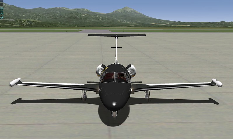
Eclipse 550 Jet Plugin
Recently, I installed the top-ranked free aircraft addon on x-plane.org, the Eclipse 550. After trying it out, I was quite impressed, so I wanted to recommend it here.
Installation is straightforward. Log in to x-plane.org, click the download link in the URL above to get the
Eclipse 550-v1-1zip file, and extract it to theX-Plane 11/Aircraft/General Aviationfolder. Then, launch X-Plane and select the aircraft.Exterior of the Eclipse 550:
-
Airliner Cockpit Secrets 5.5 Initiating Descent
In Section 5.3, when summarizing the Standard Instrument Arrival Procedure, it was mentioned that based on the position and altitude information of the initial arrival waypoint, and by referencing the Estimated Time of Arrival (ETA), fuel consumption rate, engine performance, and wind direction/speed, the pilot can configure the engine parameters and descent rate for the descent phase.
For example, the KAIHO arrival procedure starts at the ADDUM waypoint located in the Pacific Ocean, with a minimum enroute altitude of 10,000 feet. To descend from cruise altitude to ADDUM, the Flight Management Computer (FMS) calculates that the aircraft needs to begin descending from a point 200 kilometers west of ADDUM.
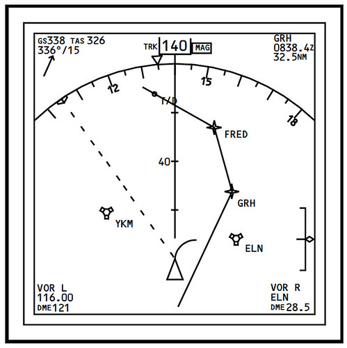
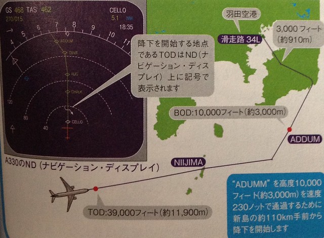 Generally, this point is called the Top of Descent (TOD) or T/D for short. It can be seen on the Navigation Display (ND) in map mode. In the Airbus 330 image above, it is represented by a bent arrow, located between the CELLO and CHALK fixes. Additionally, the start of the arrival is referred to as the Bottom of Descent (BOD).
For instance, in the Boeing 777’s ND, the location of T/D is directly marked by a dot on the flight path.
Generally, this point is called the Top of Descent (TOD) or T/D for short. It can be seen on the Navigation Display (ND) in map mode. In the Airbus 330 image above, it is represented by a bent arrow, located between the CELLO and CHALK fixes. Additionally, the start of the arrival is referred to as the Bottom of Descent (BOD).
For instance, in the Boeing 777’s ND, the location of T/D is directly marked by a dot on the flight path.
-
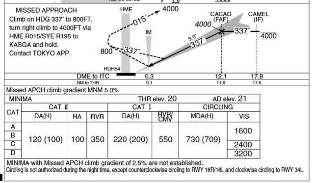
Exploring the Cockpit of an Airliner 5.4 Instrument Approach Charts
Let’s briefly summarize the instrument approach procedure using the approach chart, taking the ILS Z RWY34L (CAT II) procedure at Tokyo International Airport as an example.
Approach refers to the process of aligning the aircraft with the Runway during Descent. During the approach phase, the aircraft must adjust its altitude and align with the Runway to avoid ground obstacles. Pilots must maintain high concentration to operate accurately; therefore, approaches have strict standards and operating procedures. The “ILS Z RWY34L (CAT II)” mentioned above refers to the first (Z, with the second named Y and the third named X) instrument approach procedure name when entering Runway 34L at Tokyo International Airport.
-
X-Avionics Xavion-SIM iPad Software
X-Avionics is a paid iPad Electronic Flight Instrument System (EFIS) software developed by Austin Meyer, the creator of X-Plane, designed for real-world flight. It serves as an effective EFIS, displaying a wealth of flight data on the iPad. Furthermore, it can automatically search for the nearest airports and calculate the landing track, making it a truly intelligent pilot assistant software.

Here is some good news: X-Avionics has now released a trial version that can be used in conjunction with X-Plane. If you own an iPad, I highly recommend installing this free app—Xavion-SIM.
-
Airliner Cockpit Secrets 5.3 Standard Instrument Arrival Procedures
The approach briefing dialogue discussed in the previous section was based on radar vectoring. Generally, when traffic volume is high, air traffic control (ATC) issues specific headings, altitudes, and speeds to each aircraft to maintain safe separation between flights; this is known as radar vectoring.
However, when traffic volume is low, Standard Instrument Arrivals (STARs) are often used. A STAR provides a method for an aircraft to transition from the en route phase to the terminal area flight. Generally, a STAR terminates at the Initial Approach Fix (IAF). The benefit of using a STAR is that it graphically depicts the arrival route structure and simplifies communication between ATC and pilots, eliminating verbose arrival instructions.
-
Airliner Cockpit Exploration 5.2 Approach Briefing
“The approach briefing is a statement by the pilot flying to the other pilot before a certain phase or maneuver of flight, outlining the intended implementation. It is a brief review of normal and non-normal procedures, control techniques, notes, and crew coordination for a specific action. This ensures crew members are clear on their responsibilities—how to handle normal situations and how to coordinate during abnormal ones—much like a pre-war rehearsal.
