Airliner Cockpit Secrets 6.9 Docking at Jet Bridge
It has been over half a year since this series was last updated; I must apologize. Recently, I took a few photos of a marshaller guiding an aircraft to a Jet Bridge. Although they were taken with an iPhone before boarding, the results are quite satisfactory, so I can finally continue the updates.
First, let’s look at some common hand signals used by the marshaller while holding up signal bats,
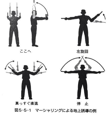 From the pilot's perspective,
for example, when guiding the aircraft to turn left, as shown in the legend in the top right of the image above,
the marshaller's right arm is extended flat, and the left arm swings upward continuously.
The speed of the swinging tells the pilot the magnitude of the turn rate adjustment needed.
The pilot needs to closely observe the marshaller's gestures, coordinate with the rhythm of the guidance,
and gently control the nose wheel steering to keep the aircraft taxiing directly above the **lead-in line**.
From the pilot's perspective,
for example, when guiding the aircraft to turn left, as shown in the legend in the top right of the image above,
the marshaller's right arm is extended flat, and the left arm swings upward continuously.
The speed of the swinging tells the pilot the magnitude of the turn rate adjustment needed.
The pilot needs to closely observe the marshaller's gestures, coordinate with the rhythm of the guidance,
and gently control the nose wheel steering to keep the aircraft taxiing directly above the **lead-in line**.
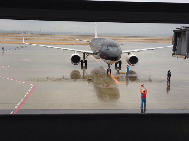
The photo below was taken while the marshaller was guiding an A320 aircraft through a left turn,
at Kansai International Airport in Osaka.
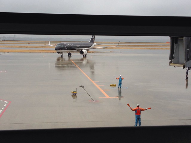
According to the “旅客機操縦マニュアル (Aircraft Operating Manual)” I have at hand, pilots should control the aircraft’s ground taxi speed to not exceed 5 knots, and operate the steering wheel gently. This is because if the steering is too abrupt, passengers in the cabin will feel a swaying motion, which is very uncomfortable. However, a skilled pilot’s maneuvering will make passengers feel unaware that the aircraft is adjusting left and right on the ground.
After the aircraft turns towards the Jet Bridge, the marshaller continues to fine-tune its forward direction,
as shown in the figure below.
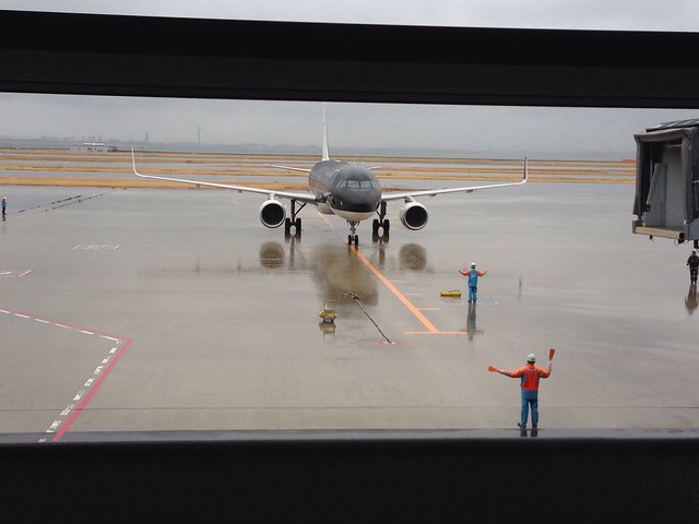 The aircraft’s nose wheel is basically on the lead-in line, but it still needs a slight adjustment to the right.
Therefore, the marshaller slowly swings their right arm to guide the aircraft to align completely with the Jet Bridge.
The aircraft’s nose wheel is basically on the lead-in line, but it still needs a slight adjustment to the right.
Therefore, the marshaller slowly swings their right arm to guide the aircraft to align completely with the Jet Bridge.
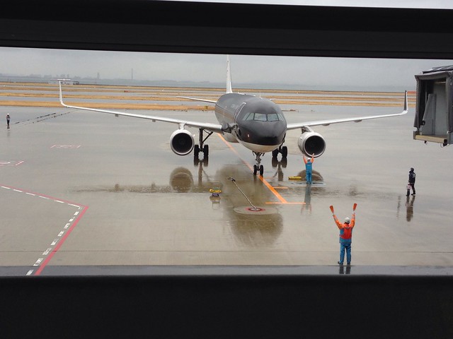
As the aircraft gradually approaches the Jet Bridge, the marshaller raises both hands high,
slowly swaying the signal bats left and right, as shown in the bottom left of the diagram above, guiding the aircraft to taxi slowly forward.
If the swinging speed remains constant, it means the pilot needs to maintain the current speed. If the swinging speed increases, it means the pilot needs to moderately increase the speed. If the swinging speed gradually slows down, it means the speed is slightly too fast, and the pilot needs to decelerate moderately. At this moment, the pilot needs to lightly apply the brakes to coordinate with the movements of the marshaller’s arms, but absolutely must not bring the aircraft to a stop. Because of inertia, once a massive airliner stops, it is necessary to increase the throttle again to generate forward Thrust, and within a very short distance, the speed cannot be too high, which would be a very difficult maneuver.
As the aircraft gets closer to the Jet Bridge, the speed of the marshaller’s arm swinging gets slower and slower.
The pilot continues to brake lightly, and the aircraft moves forward slowly, entering a state where it can stop at any time.
 Then the marshaller extends both arms horizontally and slowly raises them until they are above the head, as shown in the bottom left of the top diagram.
When the hands are crossed, it means the aircraft has reached the stopping position.
At the same time, the pilot must firmly press the brakes to prevent the aircraft from overshooting the parking spot.
Then the marshaller extends both arms horizontally and slowly raises them until they are above the head, as shown in the bottom left of the top diagram.
When the hands are crossed, it means the aircraft has reached the stopping position.
At the same time, the pilot must firmly press the brakes to prevent the aircraft from overshooting the parking spot.
After the aircraft has stopped securely, the ground crew will place chocks in front of and behind the wheels, and the pilot can begin the engine shutdown procedure.
Besides manual guidance, many airports today are equipped with a Visual Docking Guidance System.
Pilots can control the aircraft to taxi into the parking stand based on the instructions on the display screen ahead.
The Visual Docking Guidance System consists of a display screen and a laser scanner that measures the aircraft’s distance. The system can detect and analyze the aircraft type, use a laser to track the aircraft’s position, and display the results on the screen. The information on the display screen mainly includes: Aircraft type Information on deviation from the center taxi line Distance to the parking spot
When ground operators complete the input and verification of the aircraft type information via the manual control panel,
the system can start a self-check and begin continuous scanning.
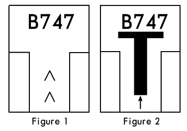
When no approaching aircraft is detected yet, the upper part of the screen displays the aircraft type, and the lower part displays yellow arrows moving continuously upward,
as shown in Figure 1 below.
 When taxiing into the boarding gate, the pilot can see from this signal that the system is activated and waiting for the aircraft,
so the pilot begins to maneuver the aircraft to complete the taxi-in operation.
When taxiing into the boarding gate, the pilot can see from this signal that the system is activated and waiting for the aircraft,
so the pilot begins to maneuver the aircraft to complete the taxi-in operation.
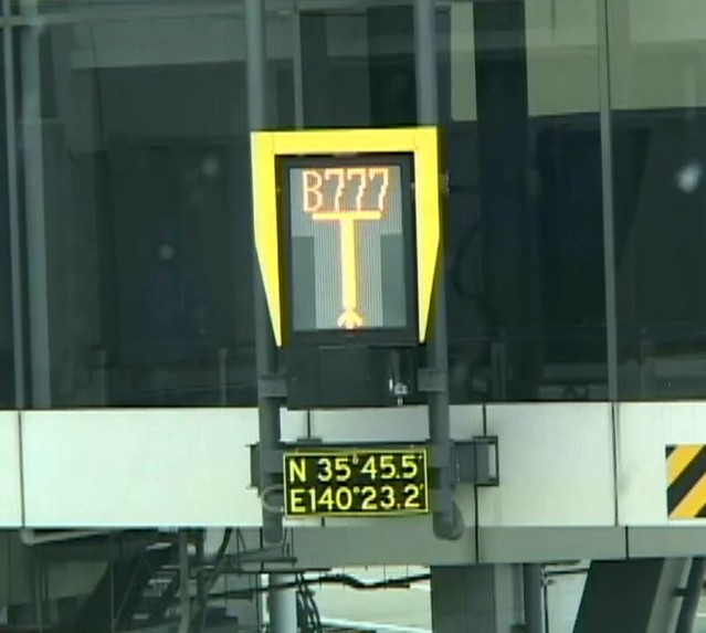
When the laser detects an approaching aircraft, the system starts to display a T-shaped symbol in the middle of the screen, with a small arrow pointing upward below the T, as shown in Figure 2 above.
When the aircraft approaches within 12 meters of the stopping position, the system starts to identify whether the aircraft type matches the type input beforehand.
If the information matches, the system will continue with the guidance.
But if the system finds a discrepancy, the upper part of the screen will alternately display the error message “STOP-ID-FAIL”,
and the middle of the screen will display two red squares as a warning.
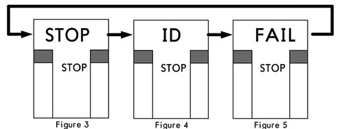 Upon seeing this message, the pilot must immediately stop the aircraft’s forward movement.
If the system detects that the aircraft’s taxi speed is too fast, the screen will display “SLOW”,
 reminding the pilot to reduce speed and prevent the aircraft from overshooting the parking spot.
If the system detects that the aircraft has deviated from the center taxi line,
a small yellow arrow pointing upward will appear on the lower left or right of the T on the screen,
indicating that the aircraft’s current position has deviated to the left or right of the center line.
At the same time, a continuously flashing red cursor appears at the top of the screen, pointing to the right or left,
reminding the pilot to adjust the Heading to the right or left.
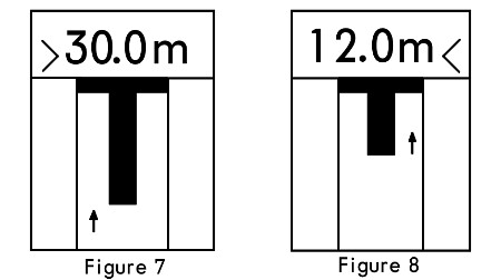
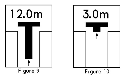
When the aircraft enters within 30 meters of the parking spot, the screen starts to display distance information, updating in meters for every meter closer, such as 30.0m, 7.0m, etc. When the aircraft enters within 2 meters of the parking spot, the numbers on the screen update in units of 0.2 meters for every 0.2 meters closer.
When the aircraft is within 16 meters of the parking spot, the length of the vertical bar of the T-shaped symbol on the screen also begins to shorten continuously.
This display not only visually represents the distance to the stopping point, but also shows the rate of closure,
helping the pilot better control the taxi speed.
The vertical bar length decreases by one increment for every 0.5 meters closer.
When the aircraft enters the parking spot, the screen starts to display “STOP”, while two red squares appear on both sides in the middle of the screen,
as shown below.

When the aircraft is correctly parked at the stand, the screen will display “OK” for several seconds, as shown in Figure 12 below.
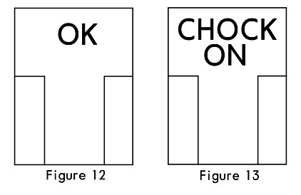
When the ground crew insert the landing gear down-lock pin and turn on the system’s “CHOCK ON” switch,
the screen will also display “CHOCK ON”, notifying the pilot that the operation is complete,
as shown in Figure 13 below.
This concludes the entire guidance process.
Prev: After Landing Procedures TOC: Table of Contents Next: Engine Shutdown Procedures