Commercial Cockpit Secrets 6.5 Landing Procedures
The Landing Procedure executed by the pilot actually begins with the ILS setup introduced in Section 6.3; this section summarizes the remaining operations.
First, the pilot notifies the cabin crew to prepare for landing, requiring passengers to stow tray tables, fasten seatbelts, return seats to the upright position, and complete all safety preparations before landing. Next, the Captain calls out Flap settings according to the Flap Schedule, and the First Officer sets the Flap lever as instructed while monitoring that the Flaps and Slats are correctly deployed.
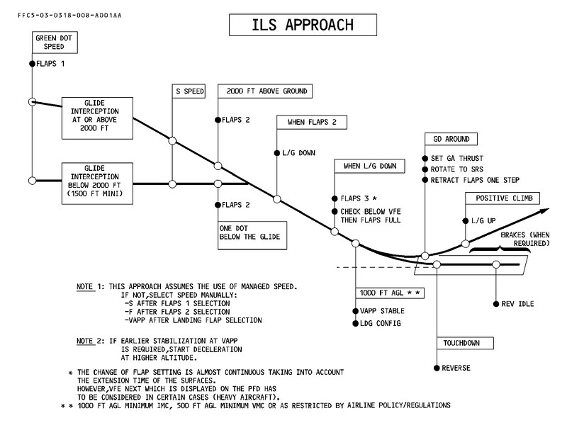
The plan for deploying Flaps can be referenced in the material below from the Airbus A340 Flight Manual. Before Glideslope Capture, they are set to Position 1. After Glideslope Capture and descending to an altitude of 2000 feet, they are set to Position 2. Following this, the Landing Gear is lowered, then the Flaps are set to Position 3, and finally to Position FULL once the speed drops below the Vref reference speed.
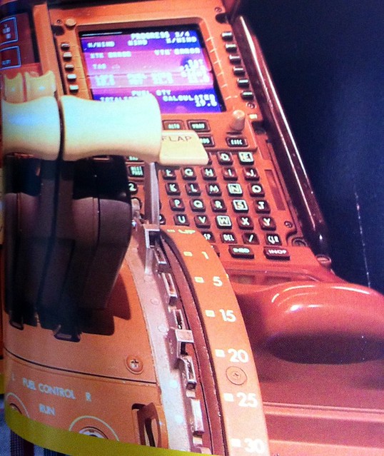
Through the two photos below, you can see the Flap positions before and after Glideslope Capture. These were taken while I was on an Airbus A320 flying to Tokyo Haneda International Airport. The approach Runway was ILS Zulu 34L. Before Glideslope Capture, the Flap position was at 15 degrees, with the aircraft over Chiba.

After aligning with the Runway direction and capturing the Glideslope, the Flap position is lowered to 20 degrees. At this point, the aircraft is flying over Tokyo Bay.

Section 2.6 introduced the fact that Flap setting positions are defined differently by Airbus and Boeing. For instance, the Airbus A330 has 5 positions (0, 1, 2, 3, FULL), while the Boeing 777 has 6 positions (1, 5, 15, 20, 25, 30 degrees).
Continuing with the Boeing 737-500 as an example, the landing procedure is summarized below. Before Glideslope Capture, lower the Flaps to position 5, then lower the Landing Gear lever. Once the green Landing Gear indicator lights illuminate, place the Flap lever to 15 and set the Engine Start Switches to the CONT (Continuous) position. Next, perform a Recall and check the System Annunciator on the right side of the MCP under the Glare Shield. Also, set the Speedbrake Lever to the ARM position and check that the SPEED BRAKE ARMED light illuminates.
After Glideslope Capture, continue to set the required positions according to the Flap schedule and set the Missed Approach altitude on the MCP. Immediately after, the Captain initiates the Landing Checklist callout, and the First Officer executes the Landing Checklist:

Below, we will specifically examine the operation of each controller and instrument required during the landing procedure.
Flap Lever
Side diagram of the Flap Lever positions on the 737.
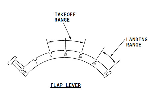 You can see that each position has a slot. When operating the Flap setting, the pilot must grip the head of the lever with their fingers, pull it upwards, move the lever to the desired position, and then release it so the lever engages into that slot.
System Annunciator (the black boxed section in the photo below); these buttons are both pressable and indicator lights.
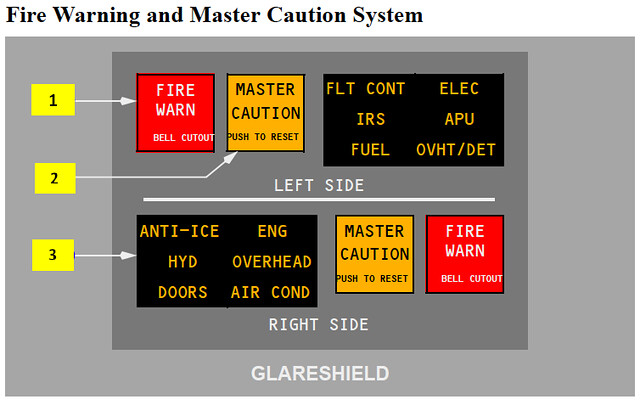 When a subsystem malfunctions, the small light corresponding to that system illuminates to alert the pilots. During the Recall check, pressing the switch causes all lights in the annunciator and the adjacent MASTER CAUTION light to illuminate, indicating that both the master warning system and individual fault systems are functioning normally.
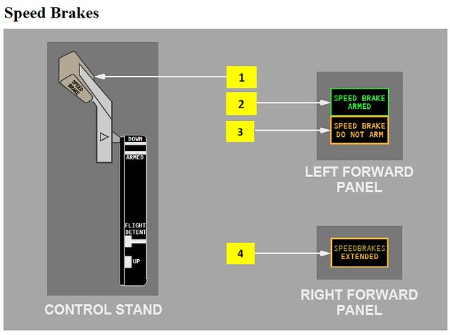
The Speedbrake Lever is located to the left of the Throttle Lever; it is a handle extending to the left.
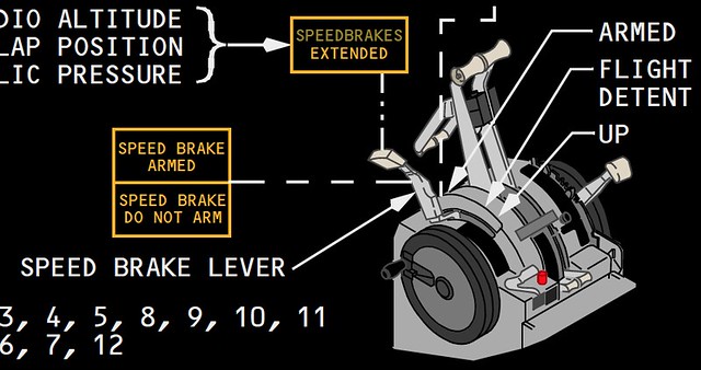
Moving the Speedbrake Lever from the Down position to the ARM position causes the adjacent SPEED BRAKE ARMED light to illuminate, as shown below.
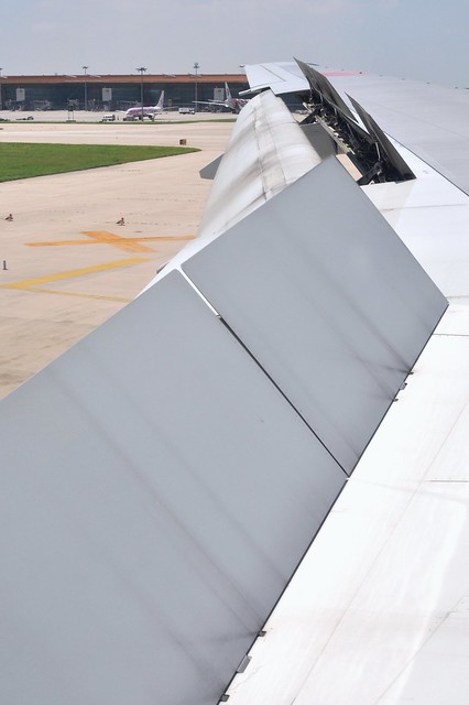
 The ARMED position means the auto-speedbrake system is activated. In this state, as soon as the aircraft touches down on the Runway, the Speedbrake Lever will automatically move to the “UP” position, causing the inboard and outboard speedbrakes to automatically deploy to the maximum position, as shown below.
The Landing Gear Lever is located between the EICAS and the First Officer’s PFD; the top of the handle is shaped like a tire, making it easy to identify.
 Pulling the Landing Gear Lever from the UP position down to DN illuminates the green Landing Gear indicator lights on the lever.
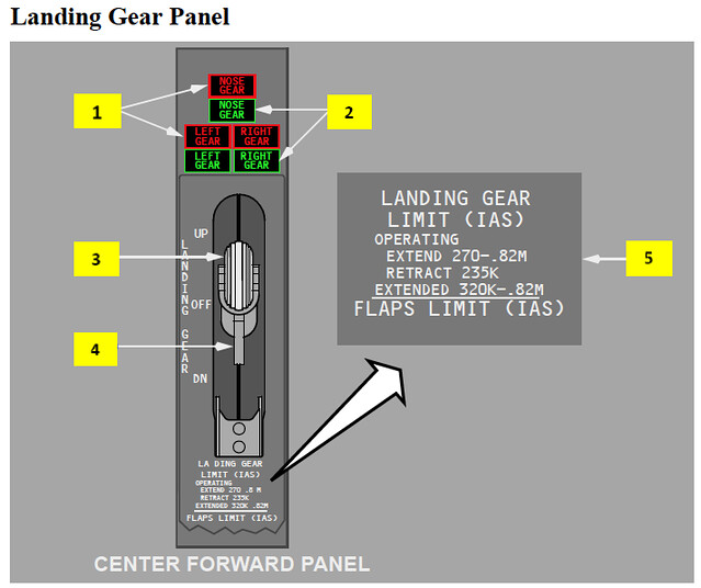 As you can see in the photo above, the nose landing gear and the two main landing gear lights at the rear are separate; if a fault occurs, checking the indicator lights will tell you which one is affected.
Once the Landing Checklist is complete, the aircraft continues to track the ILS Glideslope and reduce altitude. The vertical Descent rate is maintained at approximately 700 feet per minute, while Airspeed also needs to be constantly reduced. The pilot continues to set the target speed on the MCP and extends the Flaps accordingly. For example, if using Flap 30 for this landing, the speed will eventually be set to Vref30 + 5, such as 133 knots.
When the ILS display on the PFD confirms that the aircraft has indeed captured the Glideslope, the pilot sets the Missed Approach altitude (e.g., 4500 feet) as the altitude target on the MCP. A Go Around refers to the process where, during the descent and landing phase, if a special situation is encountered, the pilot immediately aborts the landing and transitions back to a normal Climb.
After the Flaps are lowered to the 30 position, you should notice the engine Throttle automatically increasing. This is because with the Flaps and Landing Gear extended, aerodynamic Drag increases, and the engines must provide more Thrust to maintain Lift. Therefore, even though the aircraft’s speed is reducing, passengers in the cabin will actually hear increased noise, due to the effects of increased engine Throttle and the aerodynamic Drag from the Landing Gear. At this time, the Autothrottle mode also changes from CRZ to G/A (Go Around) status. GA stands for Go Around, representing the automatic thrust mode during a Missed Approach.
Only after the Flaps are fully extended and verified is the Landing Checklist formally complete. The aircraft passes the Final Approach Fix or the Outer Marker OM, and the First Officer confirms the altitude crossing is correct; the aircraft is about to land.
End