Unveiling Airliner Flying 6.1 Control During Radar-Guided Approach
Section 5.6 summarized the dialogue during radar vectoring performed by Air Traffic Control. Below is a summary of the pilot’s specific operations during the arrival and approach phases.
When ATC issues a heading instruction, such as “Air System 115, Turn Left Heading 040”, it requires the aircraft to turn left to a heading of 040.
The pilot adjusts the HEADING knob on the Mode Control Panel (MCP) (refer to the Boeing 737 MCP diagram below),
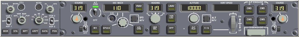 dialing the data in the display to 040. Then, the pilot presses the HDG SEL button below the knob.
At this point, the Flight Mode Annunciation (FMA) mode on the Flight Management System will change from Lateral Navigation (LNAV) to Heading Select (HDG SEL) mode.
dialing the data in the display to 040. Then, the pilot presses the HDG SEL button below the knob.
At this point, the Flight Mode Annunciation (FMA) mode on the Flight Management System will change from Lateral Navigation (LNAV) to Heading Select (HDG SEL) mode.
This change can be seen in the FMA (Flight Mode Annunciation) status transition diagram below.
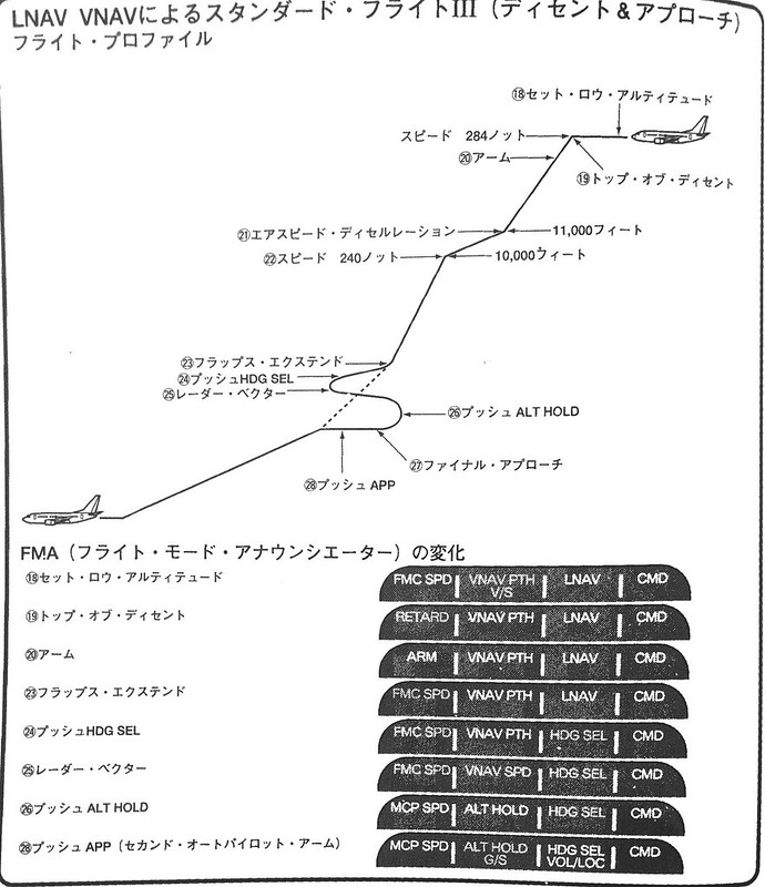 In flight state 23, after pressing HDG SEL, lateral control changes to state 24 (Heading Select).
Consequently, heading control is no longer managed by the Flight Management Computer but is manually managed by the pilot.
In flight state 23, after pressing HDG SEL, lateral control changes to state 24 (Heading Select).
Consequently, heading control is no longer managed by the Flight Management Computer but is manually managed by the pilot.
However, it is important to know that while the MCP manages the aircraft’s flight direction, the actual turning maneuver is still automatically controlled by the computer adjusting the control surfaces.
Generally, a standard turn requires the aircraft to roll into a 30-degree bank (not just moving the rudder at the vertical tail).
It utilizes the lift difference generated by the left and right ailerons to tilt the fuselage left or right, achieving the turn.
For example, to turn left, the left aileron moves up, and the right aileron moves down. This increases the lift generated by the right wing and decreases lift on the left. The imbalance of lift causes the aircraft body to tilt to the left and begin a left turn.

As the nose direction gradually approaches the target heading, the computer adjusts the ailerons to gradually reduce the bank angle. Until reaching the 040 heading (Northeast) the aircraft is returned to a level flight state.
Since radar vectoring has begun, the pilot also disables the Vertical Navigation (VNAV) mode and initiates manual altitude control mode. For instance, if the aircraft is currently in level flight at 4000 feet, the pilot presses the ALT HLD button below the ALTITUDE knob to maintain the current altitude. Correspondingly, the FMA flight mode signals also transition: the autothrottle mode changes from FMC SPD to MCP SPD, and the pitch mode changes from VNAV ALT to ALT HOLD mode. These changes are reflected in items 25 and 26 of the FMA status transition diagram above. Thus, altitude control is also disengaged from the FMC and is now directly controlled by the pilot via the MCP.
After the autothrottle mode changes from FMC SPD to MCP SPD, the speed indicator IAS/MACH on the MCP, which was previously not displayed, will illuminate, showing the current aircraft airspeed. If no adjustments are made, the computer will automatically adjust the thrust to maintain this speed. The pilot will adjust the speed according to Standard Instrument Arrival (STAR) and Standard Instrument Approach (SIAP) procedures, and deploy flaps as necessary, while ensuring the airspeed does not exceed the flap maneuvering speed limits defined by the aircraft’s structural strength.
According to regulations in the manual, the flap maneuvering speed is based on the VREF reference speed mentioned in section 5.7, varies with weight, and follows the flap schedule below to ensure the aircraft speed does not drop below the stall speed.
Taking the Boeing 737 as an example, the flap maneuvering speed using VREF at flap position 40 is: Flap Position 1: Flap Maneuvering Speed VREF + 50 knots Flap Position 5: Flap Maneuvering Speed VREF + 30 knots Flap Position 10: Flap Maneuvering Speed VREF + 30 knots Flap Position 15: Flap Maneuvering Speed VREF + 20 knots Flap Position 25: Flap Maneuvering Speed VREF + 10 knots Flap Position 30: Flap Maneuvering Speed VREF30 Flap Position 40: Flap Maneuvering Speed VREF40
Assuming a flight on a Boeing 737-500 is in the Flap 1 configuration with a maneuvering speed of 190 knots, the pilot will rotate the knob below the speed indicator to set the display value to 190.
When ATC issues an altitude instruction, such as “Air System 115, Descent and Maintain 3000”, it requires the aircraft to descend to an altitude of 3000 feet. Therefore, the pilot adjusts the ALTITUDE knob again, setting the altitude to 3000 feet, and presses the LVL CHG (Level Change) button. The computer adjusts the autothrottle again; the FMA throttle mode changes from MCP SPD to RETARD, throttles are reduced to idle, and the nose pitches down to begin the descent. Meanwhile, the pitch control mode changes from ALT HOLD to MCP SPD, so the computer controls the pitch attitude to maintain the speed at 190 knots during the descent.
When the altitude is within 100 feet of the target value, the FMA pitch control changes from MCP SPD to ALT ACQ, and the descent continues. Upon reaching the target altitude, the autothrottles automatically advance, maintaining the aircraft at 3000 feet. Consequently, the FMA pitch control changes again, from ALT ACQ to ALT HOLD, indicating the altitude hold state.
One more point regarding altitude: after the aircraft descends below 2500 feet, the onboard Radio Altimeter automatically activates, with its data displayed below the center of the PFD. The Radio Altimeter is an airborne radio device that measures the aircraft’s true altitude above ground level based on the principle of radio wave reflection.
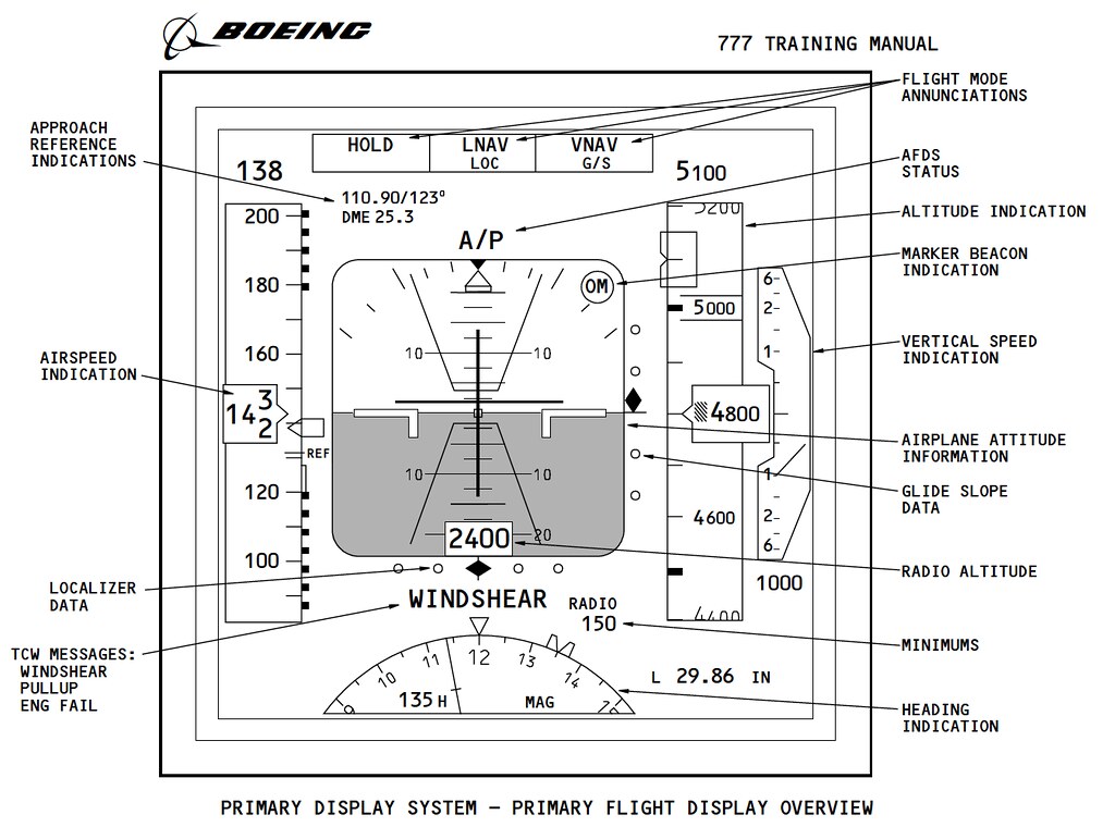 Refer to the explanation in the Boeing 777 training manual above,
the arrow at RADIO ALTITUDE points to the radio altimeter display of 2400 feet.
Refer to the explanation in the Boeing 777 training manual above,
the arrow at RADIO ALTITUDE points to the radio altimeter display of 2400 feet.
The aircraft gradually begins to approach the Final Approach Fix (FAF), and the pilot starts preparations for the ILS approach.
End
Prev: Summary of Operations During Descent TOC: Table of Contents Next: Landing Aid Systems