Airliner Cockpit Exploration 5.7 Summary of Operations During Descent
This section provides a brief summary of pilot operations during the Descent phase, using the Boeing 737 as an example.
First, pay attention to the Descent Procedure. It needs to start 80 nautical miles before reaching the Top of Descent (TOD) and be completed upon reaching 10,000 feet Mean Sea Level (MSL).
As preparation for the Descent, obtain the latest weather reports, Approach procedures, and Runway status for the destination airport via ATIS or ACARS. Use the weather radar to observe weather conditions in the Descent area, and prepare for the Approach type, airport charts, and Approach charts.
Next, the First Officer (FO) completes the landing route in the CDU and sets the landing altitude for the destination airport.
Then, the Captain and FO perform a handover of control and communications. The FO will fly the aircraft. The Captain needs to carefully check the remaining fuel and fuel balance, switch on anti-ice switches as needed, verify the Arrival and Approach procedure settings on the CDU, confirm altitude and speed restrictions for each Waypoint, confirm landing weight/VREF/QNH or QFE settings on the Approach Reference page, input the transition level/forecast wind data on the Descent Forecast page, set navigation frequencies (VOR/ILS/DME, etc.), select Autobrake (usually 1 or 2; select 3 or MAX if the Runway is short or wet), and complete the Approach Brief.
After this, the Captain and FO perform the control and communications handover again and begin executing the Descent Checklist.
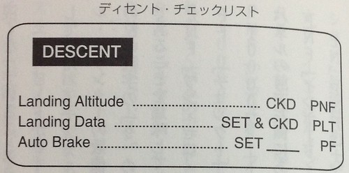 You can see the Descent Checklist includes checking the landing altitude, setting and checking landing data, and verifying the Autobrake settings.
Before reaching the TOD calculated by the CDU, the Captain will instruct the FO to request Descent clearance from Air Traffic Control. After receiving permission, set the Descent altitude for the initial fix of the arrival procedure on the MCP. In VNAV mode, the aircraft will fly to the TOD automatically calculated by the FMC and begin the Descent.
When the altitude descends to near the transition level, the Altimeter needs to be adjusted from standard pressure (QNE) to corrected sea level pressure (QNH).
 Since this setting was explained in detail in 4.3 Flight Altitude, Pressure, and Maximum Flight Altitude, I will not repeat it here.
The average vertical Descent rate of an aircraft is generally 400 meters per minute, or about 24 km/h. Therefore, descending from a cruising altitude of 10,000 meters to the ground takes approximately 25 minutes.
The upper surface of aircraft wings is equipped with devices called Spoilers (sometimes referred to as lift dumpers), divided into two parts: the Inboard Spoiler and the Outboard Spoiler. During Descent in the air, the Outboard Spoilers can be opened upwards to reduce Lift and increase air Drag, thereby achieving the goal of slowing down.
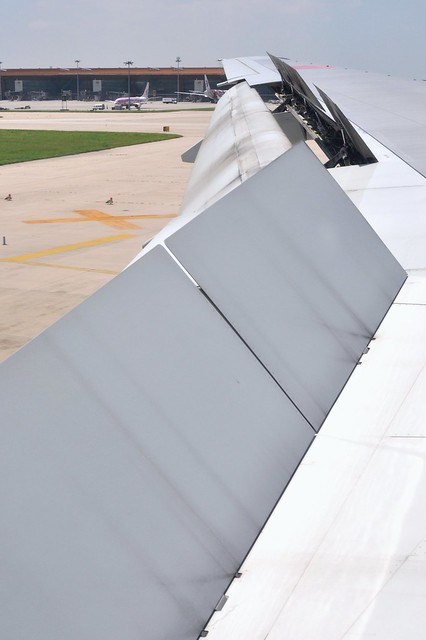
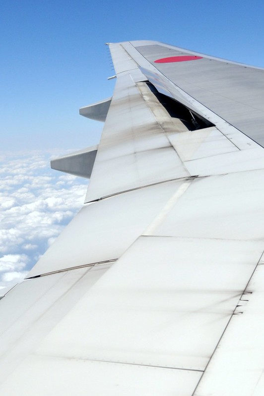 The photo above was taken while I was on an ANA Boeing 777-200 flying to Beijing Capital International Airport during the Descent. You can see the speed brake located in the middle of the wing is only partially open, but this is sufficient to give the aircraft the necessary Drag.
From another angle, this is what the Spoilers look like when opened from the rear of the aircraft.
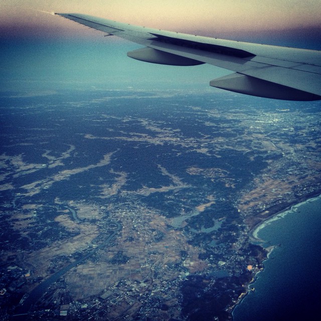 Photo taken over Chiba, Japan, during the arrival process at Narita Airport, aircraft type 777-200ER.
You can also refer to the photo below taken after landing on the Runway. You can see that both the inboard and outboard Spoilers are fully deployed and standing completely upright. This way, after touchdown, it provides significant Drag to the aircraft, causing the Lift generated by the wings to drop sharply, ensuring the fuselage and tires make full contact with the ground. Consequently, the wheel brakes also begin to function, providing greater deceleration.
However, in reality, for pilots, the main purpose of using Spoilers is not to slow down, but rather to increase the vertical Descent rate. For example, when there is a cumulonimbus cloud ahead on the Descent path, a maneuver to avoid it is required. Descent only begins after dodging the cloud, but at this point, the Top of Descent (TOD) has already passed the预定 location. To regain the intended altitude as quickly as possible, Spoilers can be used to increase the Descent rate and make up for the time lost due to the avoidance maneuver. However, be aware that using Spoilers has some drawbacks: it causes vibration and noise, which may be uncomfortable for passengers. Therefore, pilots will try to plan a Descent that avoids the use of Spoilers.
Usually, the Approach Procedure begins at the transition level and is completed before reaching the Initial Approach Fix (IAF) or before starting radar guidance.
The Approach Procedure includes setting the passenger sign, i.e., turning on the seatbelt sign (below 10,000 feet, high surface temperatures create atmospheric convection, causing Turbulence); after reaching 10,000 feet, turning on the fixed landing lights and strobe light switches (to improve visibility and reduce the chance of mid-air collisions with other aircraft or birds); setting the Altimeter at the transition altitude and cross-checking; setting required communication and navigation frequencies (VOR/ILS/DME, etc.). After completion, execute the Approach Checklist.
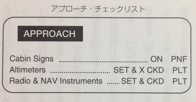 The content is as shown above, which corresponds to the various items explained in the Approach Procedure.
Additionally, pilots need to adjust their seats, fasten shoulder harnesses, and notify the cabin crew to prepare for Descent.
The content is as shown above, which corresponds to the various items explained in the Approach Procedure.
Additionally, pilots need to adjust their seats, fasten shoulder harnesses, and notify the cabin crew to prepare for Descent.
As the aircraft’s altitude continues to decrease, gradually approaching the Initial Approach Fix (IAF) (using the previous section’s example: altitude 4000 feet), the vertical Descent rate also gradually decreases, and the aircraft’s attitude begins to approach a Level Flight state.
Since the aircraft is no longer descending, the engines cannot remain at idle; the throttle must be increased to maintain sufficient Lift. Of course, this is also automatically controlled by the computer’s autothrottle. Therefore, passengers in the cabin can also perceive that the noise from the engines outside is louder than during the Descent phase. Experienced passengers will know that landing is imminent.
Finally, I will add a little more knowledge about the anti-icing systems on aircraft.
When the aircraft is flying at higher altitudes, the surface temperature of the aircraft is below 0°C. If the aircraft encounters moist air during the Descent, transparent ice or frost may form even if the ambient temperature is above freezing, affecting normal flight.
Supercooled water droplets are liquid water droplets that have not frozen at sub-zero temperatures. We all know that water freezes below zero on the ground, but this special water exists at high altitudes; because the water lacks condensation nuclei, it remains liquid even at temperatures ten or twenty degrees below zero. When an aircraft passes through a cloud containing supercooled water, the water in the cloud encounters the aircraft and freezes immediately upon finding a condensation nucleus; the aircraft fuselage serves as that nucleus.
When ice accumulates on the aircraft wings, it has a significant impact on aerodynamics. Wind tunnel tests show that when there is half an inch of ice accumulation on the leading edge of the wing, Lift is reduced by 50% and Drag is increased by 60%. In severe cases, this can cause major accidents resulting in the destruction of the aircraft and loss of life. Equally serious is engine icing; if ice forms on the engine nacelle and is ingested into the engine, it can damage critical parts like the fan blades, causing engine failure. The danger is self-evident.
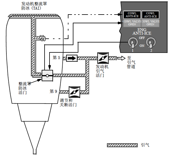
Taking the Boeing 737 as an example:
 The onboard anti-icing system generally includes subsystems for cockpit window heating, windshield wipers, probe and sensor heating, engine anti-ice, wing anti-ice, and ice detection.
The Pitot tube (static port) probes, total air temperature probes, and angle of attack vanes are critical sensors for obtaining flight data. If icing prevents them from accurately measuring speed/pressure/temperature data, the flight computer and pilots cannot correctly control the aircraft. Therefore, these devices use electric heating to prevent icing (static ports are generally unheated).
The engine anti-icing system directs high-temperature, high-pressure air from inside the engine to the front of the engine nacelle (cowling), using hot air to heat the cowling and prevent icing. The ENG ANTI-ICE switch in the cockpit controls the operation of this system.
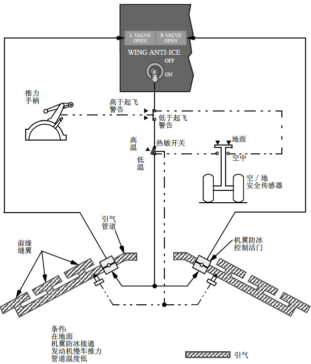
The wing anti-icing system also uses hot air from the engines. This system only provides protection for the inboard leading edge slats, not the leading edge flaps or outboard leading edge slats. It is controlled by the WING ANTI-ICE switch in the cockpit.
End Prev: ATC Communication During Descent TOC: Table of Contents Next: Control During Approach Radar Vectoring