Airliner Cockpit Secrets 5.3 Standard Instrument Arrival Procedures
The approach briefing dialogue discussed in the previous section was based on radar vectoring. Generally, when traffic volume is high, air traffic control (ATC) issues specific headings, altitudes, and speeds to each aircraft to maintain safe separation between flights; this is known as radar vectoring.
However, when traffic volume is low, Standard Instrument Arrivals (STARs) are often used. A STAR provides a method for an aircraft to transition from the en route phase to the terminal area flight. Generally, a STAR terminates at the Initial Approach Fix (IAF). The benefit of using a STAR is that it graphically depicts the arrival route structure and simplifies communication between ATC and pilots, eliminating verbose arrival instructions.
An airport often defines multiple arrival procedures based on different Runways and Headings. For example, at Tokyo International Airport, RNAV (Area Navigation) arrival procedures include ARLOG, CREAM, CACO, BACON, DATUM, NYLON, STEAM, BALAN, DARKS, DAIYA, and KAIHO. Non-RNAV arrival procedures include EGARI, SINGO, KENJI, NAGAI, etc. Standard Instrument Arrival procedure names are usually derived from Waypoints or Fixes.
Area Navigation requires aircraft to be equipped with multiple navigation systems such as GPS, FMS, and VOR/DME. It uses predetermined Waypoints and determines geographic position via latitude/longitude coordinates or the relative distance and bearing from ground-based navigation aids like VOR/DME, resulting in higher flight efficiency.
Below is a summary of Standard Instrument Arrival procedures using the KAIHO STAR chart for Tokyo International Airport.
In the header on the right, “STAR RWY34L/R” is noted, indicating this is an arrival procedure used for landing on Runways 34L and 34R.
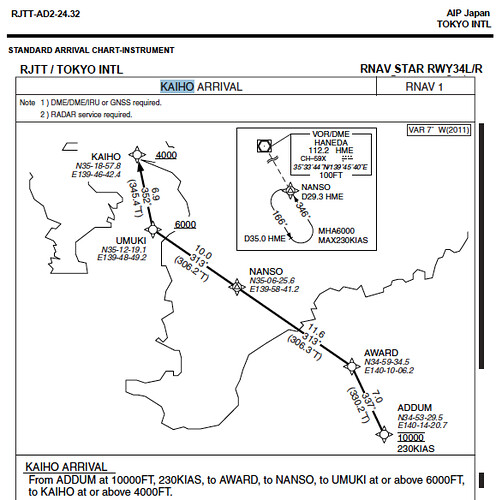
First, look at the NOTES. The procedure requires the aircraft to be equipped with DME/DME/IRU or GNSS navigation equipment and requires radar vectoring service.
Below the NOTE is the plan view of the chart. You can see the Boso Peninsula in Chiba Prefecture extending into the sea in the center of the map, and the Miura Peninsula in Kanagawa Prefecture on the left. Tokyo Bay lies between these two peninsulas. The location of Tokyo International Airport is not marked on the chart, but based on the direction of the Heading arrows, it can be inferred that the airport is in the upper left outside the chart area.
The KAIHO arrival procedure starts at the ADDUM Waypoint, marked by a four-pointed star in the Pacific Ocean in the lower right of the chart. The chart lists its coordinates and flight restrictions: a Minimum Enroute Altitude of 10,000 feet and a maximum speed of 230 knots. Based on these conditions, and referencing Estimated Time of Arrival (ETA), fuel burn rates, and engine performance, pilots can set engine parameters and the Descent rate. Generally, Waypoints for RNAV navigation are marked with four-pointed stars, while VOR/DME Fixes use triangles.
The next Waypoint after ADDUM is AWARD, also located over the sea. The chart provides AWARD’s coordinates as well as the distance (7 nautical miles) and magnetic bearing (337°) for this leg. In the upper right of the plan view, the magnetic variation for this area is noted as 7° West, and the True track of 330° is also labeled.
The next Waypoint is located on land at NANSO, in the middle of the Boso Peninsula in Chiba. Upon reaching AWARD, the aircraft must adjust its Heading to fly a track of 313° across the Boso Peninsula. After flying 11.6 nautical miles past NANSO, it proceeds to the UMUKI Waypoint located inside Tokyo Bay, 10 nautical miles ahead. Note the 6000 feet altitude marking to the right of the UMUKI Waypoint, indicating the aircraft should descend to at or above 6000 feet at this point.
Upon reaching UMUKI, the aircraft must adjust Heading again, flying north on a 352° track towards KAIHO. After 6.9 nautical miles, reaching KAIHO, the aircraft should descend to 4000 feet or above.
Additionally, the box in the upper center of the chart depicts a Standard Holding Pattern (the trajectory looks like a running track). If the aircraft does not receive Approach clearance from ATC, it must execute a left-turn Standard Holding Pattern at NANSO upon arrival. The position of NANSO can also be identified via the Haneda (HME) VOR/DME station (Frequency 112.2 MHz), located along the 346° radial inbound at a DME distance of 29.3 nautical miles.
Holding procedures are established to assist controllers with flow management at busy airports or during hazardous weather conditions, maintaining necessary separation between aircraft. A holding pattern consists of the Holding Fix, Holding Course, outbound leg length, Minimum Holding Altitude (MHA), and Maximum Holding Speed (MAX). In the chart above, the Holding Fix is NANSO, the inbound course is 346°, the holding direction is 166°, the outbound leg length is 35 nautical miles from Haneda VOR/DME, the Minimum Holding Altitude is 6000 feet, and the Maximum Holding Speed is 230 knots. Without instructions from ATC, the aircraft must continuously circle in the holding pattern, queuing for arrival sequence or waiting for weather to improve.
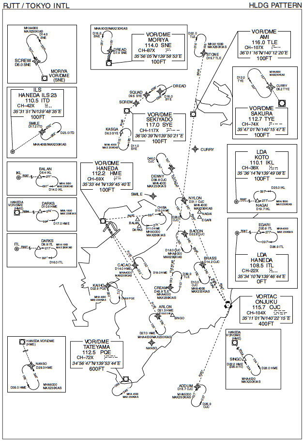
Looking at all holding procedures designated near Haneda Airport, over a dozen holding patterns are densely defined around Tokyo Bay. Since different altitudes can be assigned to each pattern, multiple aircraft can fly in the same airspace simultaneously.
Once the aircraft reaches the IAF, it enters the Approach phase. The next section will summarize how to read the Instrument Approach Chart.
Prev: Approach Briefing TOC: Table of Contents Next: Standard Instrument Approach Procedure
End