Airliner Cockpit Secrets 4.1 Basics of Navigation
Once the aircraft enters the cruise phase, pilots can finally relax a bit and ease the tension built up since takeoff. Cabin attendants also bring coffee and other beverages to the cockpit; after all, the air inside the aircraft is dry, and pilots need to stay hydrated.
While they are resting, let’s take a brief pause to look back at the journey since takeoff.
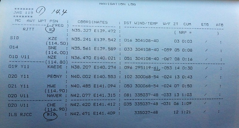
Taking flight JAS115 as an example, let’s first look at the route chart and the NAVIGATION LOG.
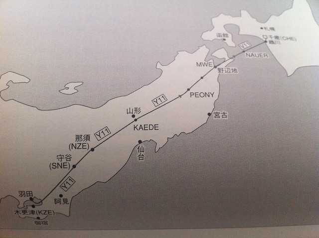
The navigation route selected by the aircraft is a Standard Instrument Departure (SID), followed by the Kisarazu KZE station, Moriya SNE station, Nasu NZE station, Yamagata KAEDE Waypoint, PEONY Waypoint, Nabetobi MWE Waypoint, the offshore NAUER Waypoint, and finally the Chitose CHE station in Hokkaido. The aircraft flies basically along the Y11 Airway. From takeoff to reaching the Moriya SNE station, it has flown approximately 50 miles. Upon reaching the Nasu NZE station, the climb to cruise altitude is complete, totaling about 100 miles (160 km), reaching an altitude of 40,000 feet (12,000 meters). The flight time required is approximately 16 minutes, as shown in the figure below.
Aviation terminology such as VOR and DME is frequently used in navigation. Here is a brief explanation.
VOR (Very High Frequency Omni-directional Range) is a radio navigation system used in aviation. It operates in the VHF band from 108.00 MHz to 117.95 MHz, hence its name. The VOR system was approved by the International Civil Aviation Organization (ICAO) in 1949 as an international standard radio navigation device and is currently one of the most widely used ground-based short-range angle measurement systems. The signals transmitted by a VOR transmitter consist of two parts: one is a reference signal with a fixed phase; the other signal’s phase varies continuously with the circular angle around the beacon, meaning the signal phase transmitted at each angle is different. The signal transmitted towards 360 degrees (pointing to Magnetic North) is in phase with the reference signal (phase difference is 0), while the signal transmitted towards 180 degrees (pointing to Magnetic South) has a phase difference of 180 degrees with the reference signal. The VOR receiver on the aircraft calculates the angle of the signal relative to the beacon based on the phase difference between the two received signals, allowing the aircraft to determine its bearing relative to the VOR station using VOR.
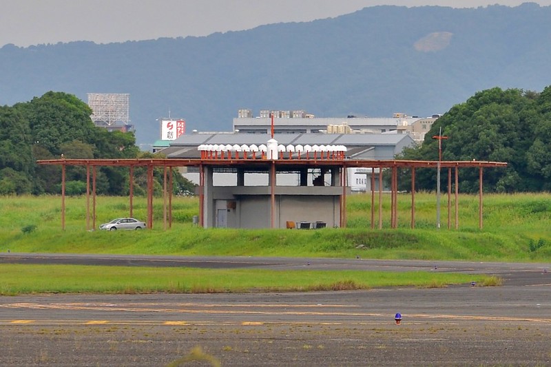
VORs are usually co-located with Distance Measurement Equipment (DME), known as a VOR-DME station. This provides the aircraft with distance information to the station in addition to directional information, allowing the aircraft’s position to be uniquely determined.
The image below shows the VOR/DME station located at Osaka International Airport, code OWE, frequency 113.9MHz, photographed by me outside Runway 32L at Osaka Airport.
On enroute charts, a VOR is represented by a compass rose, with a box next to it noting its name, frequency, identifier code, and other information.
The image below is a screenshot from the SkyVector website, showing the information for the OSAKA OWE station in the center.
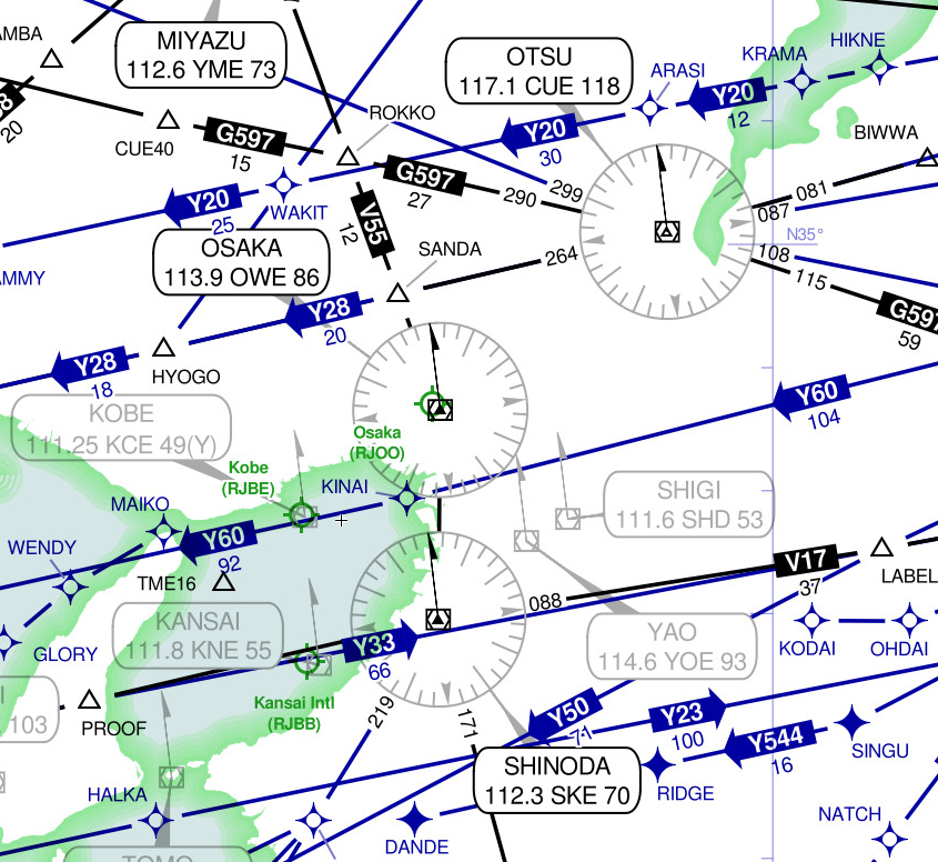
Let’s look at the OTSU station in the upper right of the image above, code CUE, frequency 117.1. You can see that this station is located at the intersection of several airways. Next to each airway, there are some numbers, such as 081, 087, 108, etc. These numbers are called VOR Radials, usually noted as R-081 and R-087, etc. R-081 means that this radial forms an 81-degree angle with the magnetic north direction of that VOR station, and R-087 is an 87-degree angle.
The aircraft flies automatically along the pre-entered route. Pilots can see their current position as well as information about various navigation stations and waypoints on the Navigation Display (ND). It is clear at a glance.
The image below shows an example of the Map Mode on a Boeing 777.

The triangle AIRPLANE SYMBOL in the lower center of the image is the aircraft’s own symbol. The zigzag solid line is the ROUTE line set in the FMS. The star-shaped markers along the route are waypoints. The dashed SELECTED TRACK line indicates the Heading set on the Mode Control Panel (MCP), pointing in the 90-degree direction.
The number in the box labeled CURRENT TRACK at the top center of the image shows the aircraft’s current direction of flight, 140 degrees (pointing to magnetic north), while the triangle marked TRK next to it displays the CURRENT HEADING, which is 135 degrees. These two data indicate that the aircraft’s forward direction is not equal to the nose pointing direction. This is due to the influence of wind direction. The Flight Management System Computer (FMS) instructs the aircraft’s nose to point slightly into the wind (windward side) to ensure the aircraft’s overall forward path remains straight. The difference between these two angle numbers is the Wind Correction Angle (WCA) mentioned in section 3.5.
The top right corner of the screen shows information regarding the next navigation point. For example, the currently active next waypoint is GRH, expected to be reached at 08:38, with a current distance of 32.5 nautical miles from that point.
The top left corner shows speed-related information. GS338 indicates a Ground Speed of 338 knots, TAS326 indicates a True Airspeed of 326 knots. The 336 degrees / 11 below shows the wind direction is 336 degrees at a speed of 15 knots. The arrow below points to the wind direction, indicating that the aircraft is basically in a direct tailwind state, so the ground speed is faster than the airspeed.
The bottom left and right of the screen display the settings for the two navigation channels, NAV1 and NAV2. The left VOR L is tuned to frequency 116.2 MHz with a DME distance of 121 nautical miles, The right VOR R is tuned to the ELN station (located below the GRH waypoint), with a DME distance of 28.5 nautical miles. In the arcs at the top of the screen, you can see the LEFT and RIGHT VOR/ADF POINTER HEADS, which are the direction pointers indicating the VOR station relative to the aircraft. The arrow points toward the station. (Note: the left and right labels in the image are incorrect and reversed). You can see that the left VOR is located at 97 degrees relative to the aircraft, and the right VOR is at 173 degrees. Thus, based on the VOR radial directions on the chart, the aircraft can proceed from waypoint to waypoint along the airway. The image below illustrates the aircraft tracking two VOR stations simultaneously and constantly correcting its current position based on data changes.

The VOR antenna is located on top of the vertical stabilizer of the Boeing 777. Since it is inside a fairing, it cannot be seen directly from the outside, but its shape can be seen in the image below.

Next, let’s introduce the VOR setup screen on the CDU of the 777.
 After pressing the NAV RAD key, the setup screen appears. The VOR navigation equipment is set in the first and second rows.
The left side is for VOR L equipment setup, and the right is for VOR R.
The first line displays the VOR identifier code and frequency, and the RADIAL field in the second line shows the required radial angle value.
The CRS in the second row is for the ILS (Instrument Landing System), which is the procedure number used during blind landings; we will explain this later.
After pressing the NAV RAD key, the setup screen appears. The VOR navigation equipment is set in the first and second rows.
The left side is for VOR L equipment setup, and the right is for VOR R.
The first line displays the VOR identifier code and frequency, and the RADIAL field in the second line shows the required radial angle value.
The CRS in the second row is for the ILS (Instrument Landing System), which is the procedure number used during blind landings; we will explain this later.
Incidentally, the ADF (Automatic Direction Finder) equipment in the third row is also a relatively simple navigation device that can indicate the direction of an NDB (Non-Directional Beacon). An NDB is a simple radio transmitter. Since the NDB signal contains bearing data, the ADF automatically finds the direction and displays the heading from the aircraft’s nose towards the NDB station on the instrument.
End
Prev: Entering Level Flight Cruise TOC: Table of Contents Next: What are flight speed indicators and what is the aircraft’s maximum speed?