Inside the Cockpit
-
Title: Secrets of Airliner Flying 4.5 About Cruising Speed
Just like cruise altitude, cruise speed must also consider fuel economy.
Similar to how a car’s performance is often judged by how many kilometers it can travel on one liter of fuel, for an aircraft, this performance can be expressed as the flight distance per unit of fuel. This is called Specific Range.
Specific Range refers to the flight distance per unit of fuel in a windless condition (e.g., data at 10,000 lbs, or approx. 4.5 tons). The value is calculated by dividing the TAS (True Airspeed) by the fuel flow.
-
Title: Exploring the Cockpit of Airliners 4.4 About Cruise Altitude
Generally speaking, the cruise altitude for short-haul domestic flights remains constant. As mentioned in previous sections, after entering the cruise phase, the aircraft maintains this altitude until the Descent and landing, barring severe weather or emergencies. However, for long-haul international routes, particularly over oceans, “Step Climb” is often employed—a method of gradually increasing the cruise altitude. Let’s look at an example of a Boeing 777-300ER flight from Tokyo to New York to see how altitudes are scheduled.
-
Title: Secrets of Airliner Cockpits 4.3 Flight Altitude, Air Pressure, and Maximum Flight Altitude
The previous section covered speed metrics; this section explains data regarding altitude.
There are two types of Altimeter on an aircraft: the barometric Altimeter and the radio Altimeter. Let’s look at the barometric Altimeter first.
We all know that as altitude increases, air density decreases, and atmospheric pressure drops accordingly. By measuring atmospheric pressure and comparing it with standard values, the absolute altitude (elevation above sea level) of the measurement location can be determined. This is the basic working principle of the barometric Altimeter. The advantage of using pressure for measurement is that the Altimeter is compact and simple in structure; however, the disadvantage is that besides altitude, changes in temperature and water vapor density also affect pressure changes. Therefore, pilots must calibrate the Altimeter based on local atmospheric conditions. This is indispensable before takeoff and landing, as the danger of landing without an accurate grasp of altitude goes without saying.
-
Title: Exploring the Cockpit of Airliners 4.2 What are the indicators of flight speed and what is the maximum speed of an aircraft?
During the cruise phase, even though the autopilot instruments on the aircraft are very advanced and pilots do not need to manipulate the controls directly, this does not mean pilots can be idle. They must constantly scan various instruments, check various flight data, and record it from time to time; they are still quite busy.
Below is a simple summary of flight data information across a few sections. First, let’s look at speed.
-
Airliner Cockpit Secrets 4.1 Basics of Navigation
Once the aircraft enters the cruise phase, pilots can finally relax a bit and ease the tension built up since takeoff. Cabin attendants also bring coffee and other beverages to the cockpit; after all, the air inside the aircraft is dry, and pilots need to stay hydrated.
While they are resting, let’s take a brief pause to look back at the journey since takeoff.
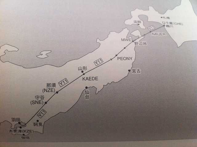
Taking flight JAS115 as an example, let’s first look at the route chart and the NAVIGATION LOG.
-
Title: Into the Level Flight Cruise
At this point, the aircraft leaves the Tokyo North Kanto Area Control Center and begins to enter the Northeast Area. Taking the Boeing 777-200 “Air System 115” flight as an example, 16 minutes after takeoff, the aircraft has reached the Nasu area in Tochigi Prefecture, passing the NZE VOR navigation aid.
It has reached an altitude of 39,000 feet.
As seen in the image above, the aircraft entered the Y11 Airway of R-NAV (Area Navigation) starting from the Moriya SNE navigation aid, and will continue north along this airway all the way to the Chitose navigation aid in Hokkaido.
-
Airliner Cockpit Exploration 3.7 ATC Handoff to Center, Continue Climb
First, let’s take Air System Flight 115 from Tokyo Haneda Airport to Hokkaido Sapporo New Chitose Airport as an example again. Let’s look at the Air Traffic Control (ATC) process required for this flight from takeoff to cruise and landing:
1 Haneda Airport: Delivery Control — Ground Control — Tower Control — Departure Control 2 Area Control: Tokyo Control Area — Sapporo Control Area 3 New Chitose Airport: Approach Control — Tower Control — Ground Control
-
Title: Unveiling Airliner Cockpit Secrets 3.6 ATC Handover to Departure Control, Entering VNAV Mode
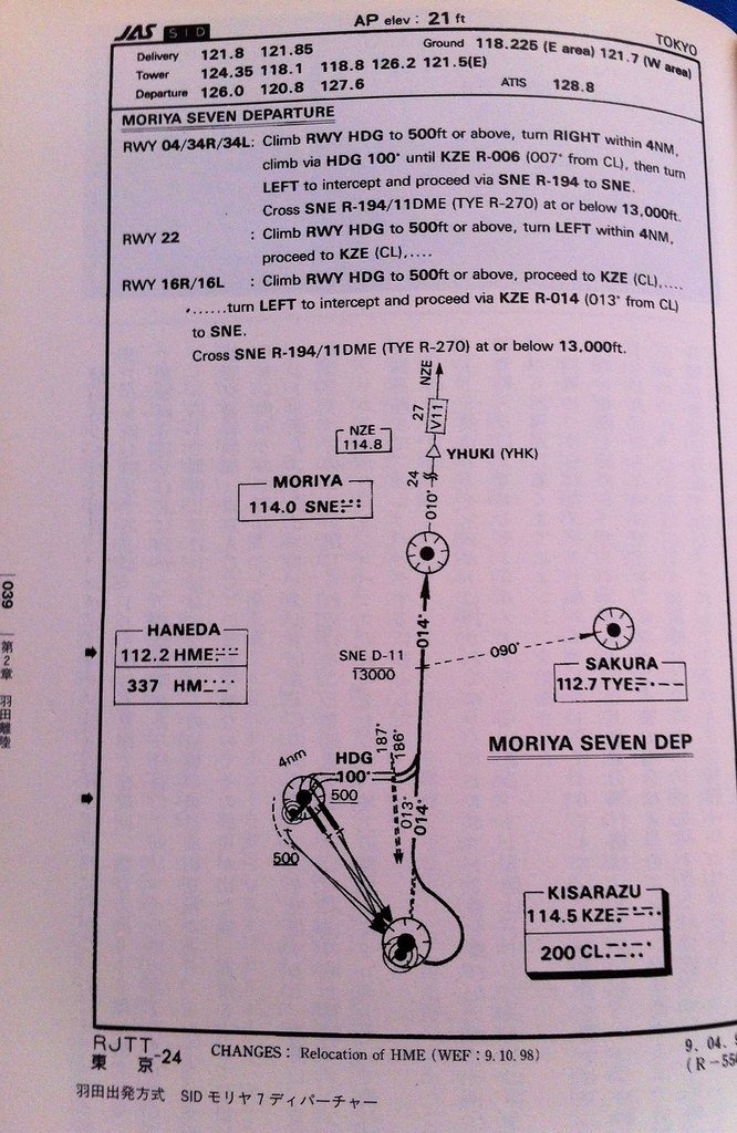
Taking AirSystem Flight 115 as an example, the aircraft follows the Moriya 7 Departure procedure at Haneda Airport. It first flies along the Runway (16R) direction to the KZE (KISARAZU) waypoint at the bottom right of the chart, then automatically banks left 30 degrees, turning to a 14-degree direction (basically close to due north) to fly towards the SNE (MORIYA) waypoint.
At this point, after the Tower controller confirms the aircraft’s departure is correct, they instruct the pilot to contact Departure Control: “Air System 115, Contact Departure” This means “Air System 115, contact Tokyo Departure” The First Officer replies “Departure, Air System 115” Meaning “Contacting Tokyo Departure, Air System 115” Then, tunes the radio frequency to Departure Control 120.800MHz, and calls: “Tokyo Departure, Air System 115, Leaving 1800” This means “Tokyo Departure, this is Air System 115, passing through 1800 feet” The controller replies “Air System 115, Tokyo Departure, Radar Contact, Turn Left Heading 020, Vector to Moriya, Climb and Maintain 210” This means “Air System 115, this is Tokyo Departure, radar contact, turn left heading 020, radar vector to Moriya, Climb and Maintain 21000 feet” The First Officer reads back: “Left 020, Direct 210, Air System 115” Meaning “Turn left heading 020, maintain 21000 feet, Air System 115”.
-
Title: Uncovering the Mysteries of Airliner Cockpits 3.5 Engage Autopilot
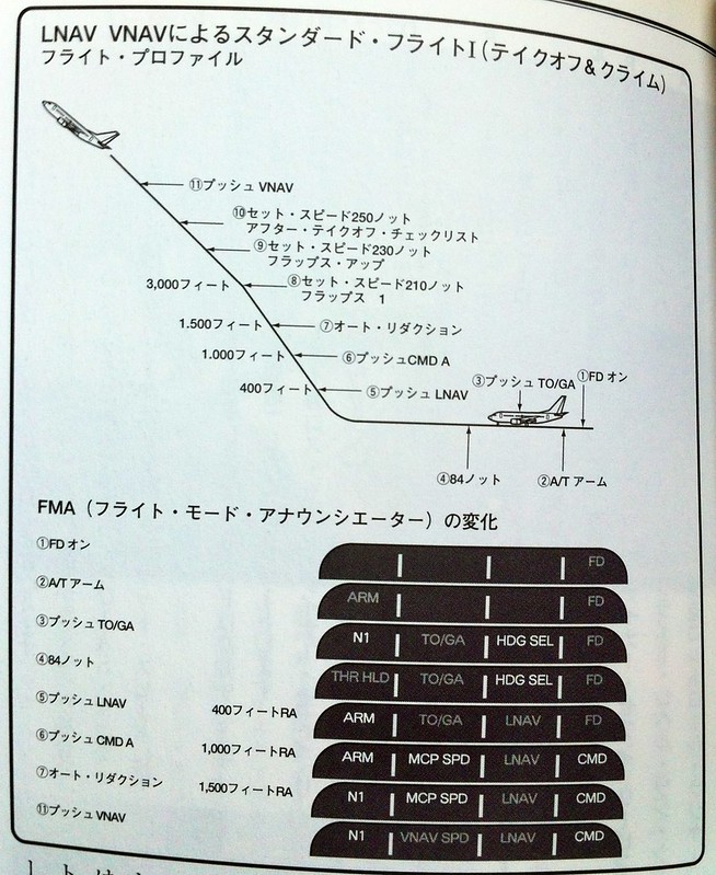
The aircraft continues to climb. The number on the radio altimeter exceeds 400 feet (using the 737-500 from the airliner pilot manual as an example). At this point, the LNAV (Lateral Navigation) mode can be engaged. The Captain instructs the First Officer to press the LNAV button on the MCP.
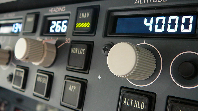
Consequently, in the mode annunciation at the top left of the PFD, the Heading setting changes from HDG SEL to LNAV, and the flight mode enters Phase 5 as shown in the figure below.
-
Title: Secrets of Airliner Flying 3.4 Gear Up
Based on the Boeing 737-500 Operating Manual from the “Airline Pilot Handbook,” let’s continue discussing the operations after the aircraft lifts off the ground.
The previous section mentioned that the Captain should keep both feet off the rudder pedals and use only the control yoke or stick to control the aircraft’s pitch and roll attitudes.
You might ask: Isn’t the rudder necessary to control adverse yaw during rolls? Isn’t it important to “call the ball” by keeping the inclinometer centered in the Turn Coordinator?
-
Title: Airliner Cockpit Secrets 3.3 Takeoff and Liftoff
As the aircraft’s speed continues to increase, a green arrow known as the speed trend vector will appear on the speed strip on the left side of the PFD.
 It indicates the current acceleration of the aircraft; the arrow pointing up shows the aircraft is accelerating, while down indicates deceleration.
The speed pointed to by the arrow is the predicted aircraft speed value 10 seconds in the future.
By observing the speed trend vector, the pilot can know the future speed trend of the aircraft, which is particularly helpful for control during the Takeoff and Departure phases.
It indicates the current acceleration of the aircraft; the arrow pointing up shows the aircraft is accelerating, while down indicates deceleration.
The speed pointed to by the arrow is the predicted aircraft speed value 10 seconds in the future.
By observing the speed trend vector, the pilot can know the future speed trend of the aircraft, which is particularly helpful for control during the Takeoff and Departure phases. -
Title: Airliner Cockpit Secrets 3.2 Takeoff Roll
Based on the weather and traffic conditions for the day, once the takeoff method has been decided, we finally enter the formal takeoff roll phase.
The Captain moves their left hand from the steering tiller to the control yoke, while their right hand remains on the engine thrust levers. (Note: Boeing aircraft use a control yoke, while Airbus uses a side-stick, located on the pilot’s outer side, as shown below.
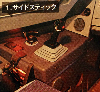
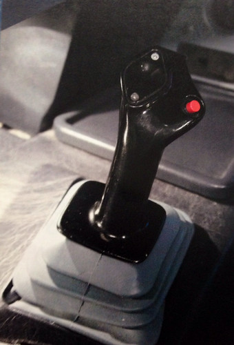 )
) -
Title: Unveiling Airliner Cockpit Secrets 3.1 3 Types of Takeoff Methods
Generally speaking, there are three takeoff methods for aircraft. Here is a brief introduction.
Normal Takeoff Method
The aircraft stops on the Runway with the nose facing the center line. While holding the brakes, push the thrust lever forward to N1 40%. After confirming stable engine operation, release the brakes and the aircraft begins to taxi. When the airspeed reaches 60 knots, set the Thrust to takeoff Thrust.
This method is primarily used in conditions such as crosswinds, wet Runways, or slippery Runways covered with ice or snow. Since it is crucial to maintain the stability of the nose Heading in these situations, this method of aligning with the Runway before applying full power is beneficial for maintaining direction. Additionally, the takeoff roll distance listed in aircraft performance specifications refers to data from this type of takeoff.
-
Title: Secrets of Airliner Flying 2.7 Takeoff Clearance
While the aircraft is taxiing, the First Officer tunes the communication frequency to the Tower band and contacts the Tower Controller: “Tokyo Tower, Air System 115, with you”
This means: “Tokyo Haneda Tower, this is Air System 115.”
The Tower Controller replies: “Air System 115, Tokyo Tower, Number 2”
Which means: “Air System 115, Tokyo Haneda Tower, you are number two for takeoff.”
Consequently, the First Officer reads back: “Number 2.”
-
Title: Exploring the Airliner Cockpit 2.6 About Flaps
In the previous section, it was mentioned that flaps should be preset to the takeoff position before taxiing. Why is this?
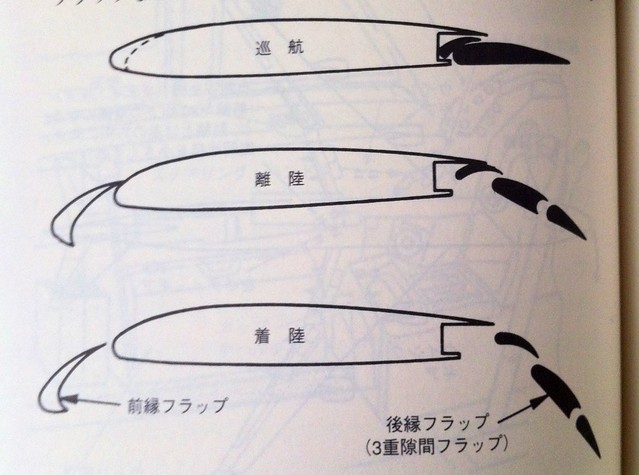
First of all, flaps are devices mounted on the trailing edge or leading edge of the wing that can deflect downward or (and) slide backward (forward), used to increase Lift. Depending on the installation location and specific function, flaps are divided into trailing edge flaps and leading edge flaps.
-
Title: Inside the Cockpit 2.5 Operations During Ground Taxiing
Below is an introduction to some operations involved in taxiing on the ground, covering aircraft turning and flight control surface checks.
When turning on the ground, the rudder pedals and the tiller must be used simultaneously. The control devices regulate the nose wheel steering via a hydraulic system. Some large aircraft, such as the Boeing 747/777 and Airbus 380, also have steering devices on their rear wheels.
In the pre-flight procedures section, it was mentioned that the rudder pedals are used to control the rudder on the vertical tail to make the aircraft turn in the air. In fact, they can also control the nose wheel, so pressing the rudder pedals on the ground allows the aircraft to turn. However, rudder pedal control only allows for slow turns at very small angles; essentially, you can only execute very wide turns. In reality, 90-degree turns are frequently required at airports, and relying solely on the rudder pedals is far from sufficient. The tiller must be used.
-
Inside the Cockpit 2.4 Ground Taxiing Taxi
The aircraft is pushed by the tug to the end of the Apron, and the ground crew contacts the flight deck again:
Ground Crew: “Flight deck, set parking brake.” Captain: “Brakes set.”
 Consequently, the ground crew removes the tug’s tow bar from the nose landing gear, sets the wheel chocks again,
 and the tug moves away from the aircraft.
 (Photo above taken at Chubu Centrair International Airport)
 -
Title: Inside the Airliner Cockpit 2.3 Push Back from the Gate and Engine Start
After the pilot obtains the clearance and completes the pre-departure 5-minute preparations (pre-start procedures), they can request pushback from Ground Control, for example:
Pilot: “Tokyo Ground, Air System 115, request push back, spot 2, information F”
This means: “Tokyo Ground Control, this is Air System 115, requesting pushback from Gate 2, we have Information F (Foxtrot).”
Upon receiving this radio request, the airport Ground Controller will check the traffic congestion on the Apron. If there are no other aircraft moving nearby, or if the movement of this flight will not affect other aircraft, they will reply:
-
Title: Airliner Cockpit Exploration 2.2 Standard Instrument Departure SID
In the previous section 5 Minutes Before Departure, it was mentioned that Air Traffic Control notified the pilot to use the Moriya 7 Departure procedure. So, what exactly is a Departure procedure?
Airplanes flying in the air are not without traffic rules. Because there are numerous airlines, especially at major airports where planes take off and land every few minutes. Similar to ground traffic, if there were no set of traffic rules to manage it, aircraft operations would be extremely dangerous. Therefore, many routes are established in the air. Although we cannot see these routes with the naked eye like roads on the ground, pilots must strictly follow the regulations to execute their flight missions. The routes and procedures set up for departing aircraft are called Standard Instrument Departures (SIDs).
-
Inside the Cockpit 2.1 5 Minutes Before Departure
While the pilot performs pre-flight preparations inside the cockpit, the ground crew is also busy preparing for the flight.
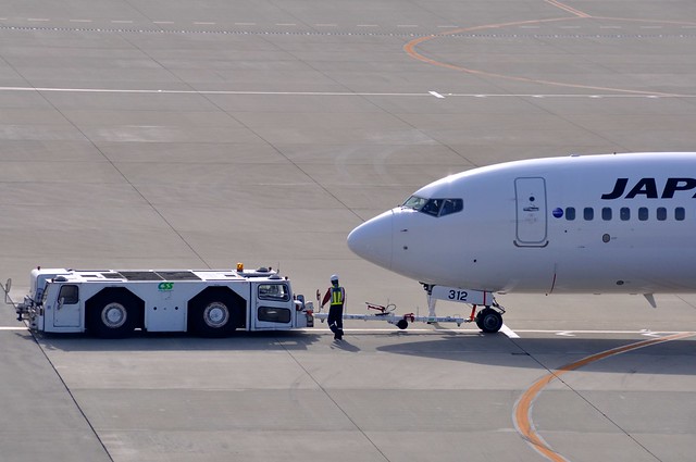
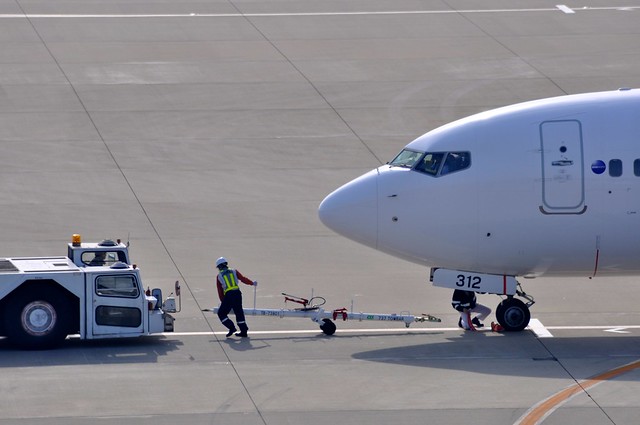
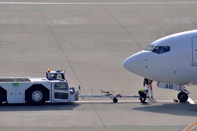
For example, they disconnect the power supply cable, ensure catering trucks, fuel trucks, and cargo dollies are moved away from the aircraft, and connect the tow tractor to the nose landing gear.
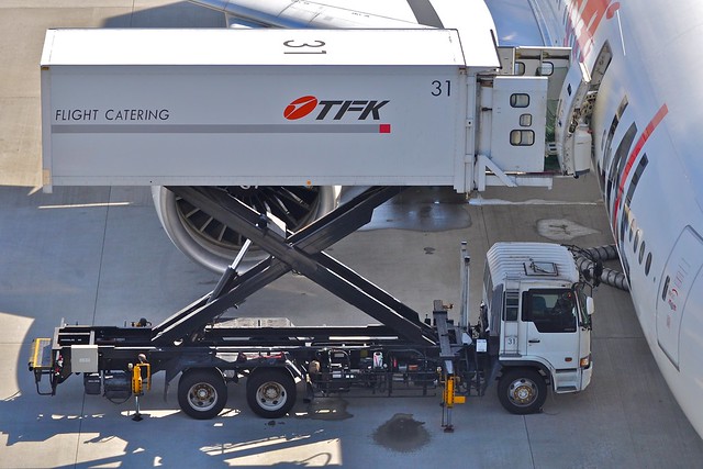 Catering truck, photographed by me at Tokyo International Airport.

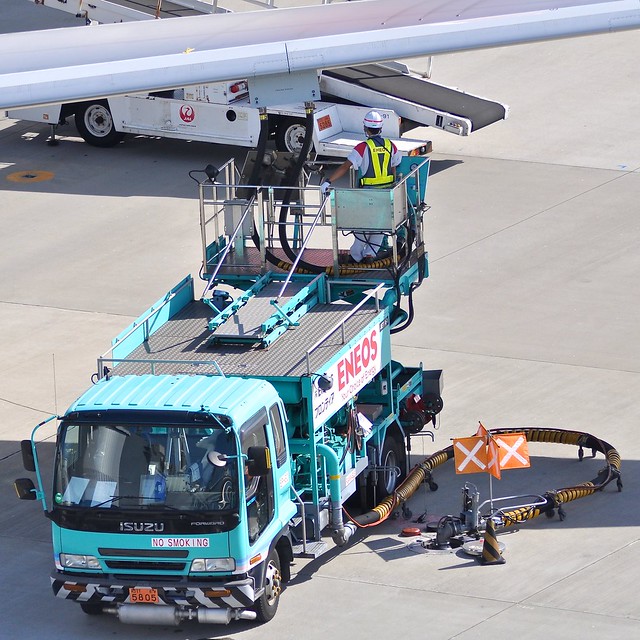 Fuel truck, photographed at Tokyo International Airport.
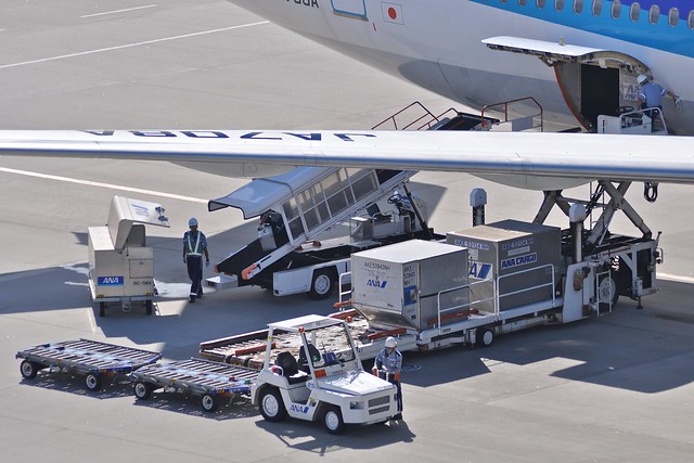 Cargo dolly, photographed at Tokyo International Airport.
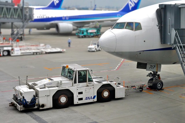 Tow tractor, photographed at Tokyo International Airport.
 Ground crew disconnecting the ground power cable from a Boeing 777, photographed at Hiroshima Airport.
Once all vehicles and equipment that could obstruct movement are removed from the vicinity of the aircraft, the ground preparation is complete.