Inside the Cockpit
-
# Secrets of Airliner Flying 6.10 Shutdown Procedure
Once the aircraft has come to a complete stop, the flight crew initiates the final shutdown procedure, starting with setting the Parking Brake.
The Captain fully depresses the toe brakes at the front of the rudder pedals while simultaneously pulling up the Parking Brake handle located at the lower left behind the control stand. The red Parking Brake warning light to the right of the handle then illuminates, confirming that the brake is set, allowing the Captain to remove their feet from the rudder pedals.
-
Airliner Cockpit Secrets 6.9 Docking at Jet Bridge
It has been over half a year since this series was last updated; I must apologize. Recently, I took a few photos of a marshaller guiding an aircraft to a Jet Bridge. Although they were taken with an iPhone before boarding, the results are quite satisfactory, so I can finally continue the updates.
First, let’s look at some common hand signals used by the marshaller while holding up signal bats,
-
Unveiling Airliner Cockpit Secrets 6.8 Post-Landing Procedures
In the previous section, we reduced the ground speed to below 10 knots and prepared to exit the active Runway. At this point, the Tower should have issued instructions for the taxi route to the parking gate. Continuing with flight Air System 115 as an example:
Tower: “Air System 115, Turn Right B9, Taxi Down Runway 19L, A10” Pilot: “Right, B9, Taxi Down Runway 19L, A10, Air System 115”
The taxi route here involves turning right at exit B9, taxiing down Runway 19L to exit A10.
-
Secrets of Airliner Flying 6.6 Go-around
Before landing, if unexpected circumstances occur that lead the flight crew to determine that continuing the Descent for landing would pose safety issues, the pilot must decisively execute the Go Around procedure.
These situations include:
- After reaching the Decision Height (DH) (for Precision Approach) or the Missed Approach Point (MAPT) (for Non-Precision Approach), the Runway and indicator lights are still not visible, and the required visual reference cannot be established.
- A failure in airborne equipment or ground navigation equipment prevents the provision of normal navigation accuracy.
- The Runway Visual Range (RVR) during the landing process cannot meet landing requirements, such as due to the influence of advection fog. Advection fog is formed when warm, moist air moves over colder land or water surfaces, cooling from below. It usually occurs in winter, lasts for a relatively long time, covers a large area, and is dense with significant thickness, sometimes reaching several hundred meters.
- When crosswinds or headwinds are too strong.
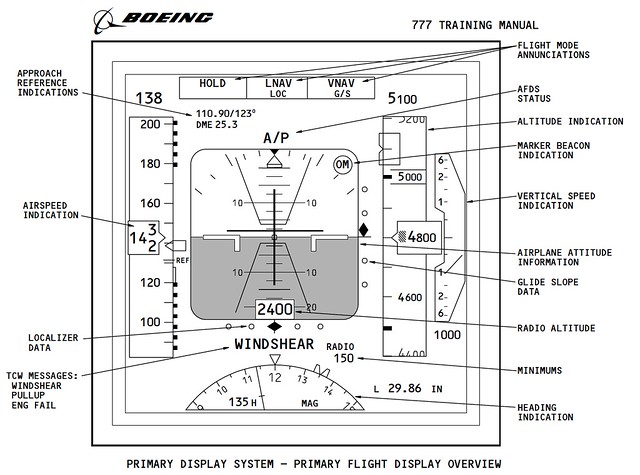
- When a wind shear warning occurs during the Approach. Modern airliners are generally equipped with wind shear detection and warning systems. If the aircraft suddenly starts shaking violently, or the wind direction and speed change significantly, the wind shear warning in the cockpit will sound, with the voice prompt “WIND SHEAR, GO AROUND,” and the warning text “WINDSHEAR” will also appear on the Primary Flight Display (PFD).
- When the Air Traffic Controller issues a Go Around instruction.
- When there are other aircraft or ground vehicles on the Runway, posing a risk of collision. Etc.
The Go Around flight path was summarized in the 5.4 Instrument Approach Charts section, so it will not be repeated here.
-
Commercial Cockpit Secrets 6.5 Landing Procedures
The Landing Procedure executed by the pilot actually begins with the ILS setup introduced in Section 6.3; this section summarizes the remaining operations.
First, the pilot notifies the cabin crew to prepare for landing, requiring passengers to stow tray tables, fasten seatbelts, return seats to the upright position, and complete all safety preparations before landing. Next, the Captain calls out Flap settings according to the Flap Schedule, and the First Officer sets the Flap lever as instructed while monitoring that the Flaps and Slats are correctly deployed.
-
Airliner Cockpit Secrets 6.4 Traffic Pattern
The Traffic Pattern (also known as circuit flying) defines the standard traffic flow for aircraft taking off and landing at an airport. This path forms a rectangular route relative to the Runway and is flown at a specific altitude. It allows pilots to anticipate and locate the position of other pilots flying near the airport. The Traffic Pattern is also a crucial training curriculum; pilots can learn essential flight skills such as Departure, Climb, Turn, Level Flight, Descent, and Landing from circuit flying.
-
Secrets of Airliner Flying 6.3 Final Approach Fix and ILS Setup
In Section 6.1, we covered the aircraft passing the Intermediate Fix (IF) and entering a state of Level Flight. In this section, we will discuss the operations during the flight from the IF to the Final Approach Fix (FAF). The relationship between the IF and FAF was introduced in Section 5.4; let’s review that here.
On the NAV/RAD page of the CDU, verify that the entered data is correct, for example, check the landing Runway azimuth is 128 degrees and the radio frequency is 110.90MHz. The image below shows a schematic of the Boeing 777 CDU display.

-
Exploring Airliner Cockpits 6.2 Landing Assistance Systems
Landing aid systems include the so-called Blind Landing System, which is the Instrument Landing System (ILS), as well as the Precision Approach Path Indicator (PAPI). In addition, transmissometers used to measure Runway Visual Range (RVR) can often be seen near the airport Runway. From a personal experience perspective, when traveling to visit relatives or on business trips by air, being able to identify the various pieces of equipment at the airport greatly enhances the enjoyment of the journey.
-
Unveiling Airliner Flying 6.1 Control During Radar-Guided Approach
Section 5.6 summarized the dialogue during radar vectoring performed by Air Traffic Control. Below is a summary of the pilot’s specific operations during the arrival and approach phases.
When ATC issues a heading instruction, such as “Air System 115, Turn Left Heading 040”, it requires the aircraft to turn left to a heading of 040.
The pilot adjusts the HEADING knob on the Mode Control Panel (MCP) (refer to the Boeing 737 MCP diagram below),
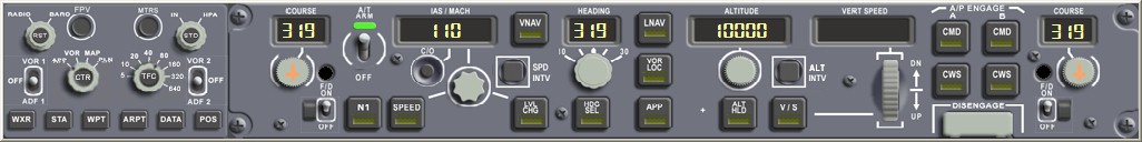 dialing the data in the display to 040. Then, the pilot presses the HDG SEL button below the knob.
At this point, the Flight Mode Annunciation (FMA) mode on the Flight Management System will change from Lateral Navigation (LNAV) to Heading Select (HDG SEL) mode.
dialing the data in the display to 040. Then, the pilot presses the HDG SEL button below the knob.
At this point, the Flight Mode Annunciation (FMA) mode on the Flight Management System will change from Lateral Navigation (LNAV) to Heading Select (HDG SEL) mode. -
Airliner Cockpit Exploration 5.7 Summary of Operations During Descent
This section provides a brief summary of pilot operations during the Descent phase, using the Boeing 737 as an example.
First, pay attention to the Descent Procedure. It needs to start 80 nautical miles before reaching the Top of Descent (TOD) and be completed upon reaching 10,000 feet Mean Sea Level (MSL).
As preparation for the Descent, obtain the latest weather reports, Approach procedures, and Runway status for the destination airport via ATIS or ACARS. Use the weather radar to observe weather conditions in the Descent area, and prepare for the Approach type, airport charts, and Approach charts.
-
Uncovering the Airliner Cockpit 5.6 ATC Communication During Descent
Prior to initiating the Descent, clearance from Air Traffic Control must be obtained. This section provides a brief summary of the communication content from the cruise phase to the Descent phase.
Continuing with the example of Air System 115 flight from Tokyo Haneda Airport to New Chitose Airport in Sapporo, Hokkaido.
As the aircraft enters the Sapporo Misawa West Area Control Center sector, Tokyo ATC needs to hand over control of the flight to the Sapporo Misawa West sector. Therefore, the controller issues the instruction: “Air System 115, Contact Sapporo Control 133.3” This means “Air System 115, contact Sapporo Misawa West Control on 133.3”. The pilot replies: “133.3 Air System 115” Then adjusts the radio communication frequency to 133.3 MHz and contacts ATC: “Sapporo Control, Air System 115, FL410” This means “Sapporo Control, this is Air System 115, current flight level is 41000 feet”. If the Sapporo Misawa West controller receives the report and confirms on radar, they will reply: “Air System 115, Sapporo Control, Roger” This means “Air System 115, this is Sapporo Misawa West Control, Roger”.
-
Airliner Cockpit Secrets 5.5 Initiating Descent
In Section 5.3, when summarizing the Standard Instrument Arrival Procedure, it was mentioned that based on the position and altitude information of the initial arrival waypoint, and by referencing the Estimated Time of Arrival (ETA), fuel consumption rate, engine performance, and wind direction/speed, the pilot can configure the engine parameters and descent rate for the descent phase.
For example, the KAIHO arrival procedure starts at the ADDUM waypoint located in the Pacific Ocean, with a minimum enroute altitude of 10,000 feet. To descend from cruise altitude to ADDUM, the Flight Management Computer (FMS) calculates that the aircraft needs to begin descending from a point 200 kilometers west of ADDUM.
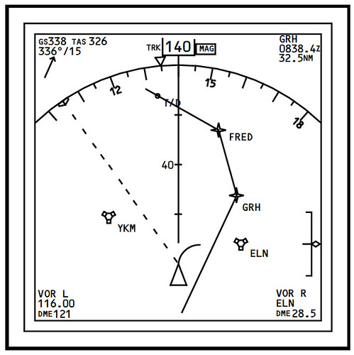
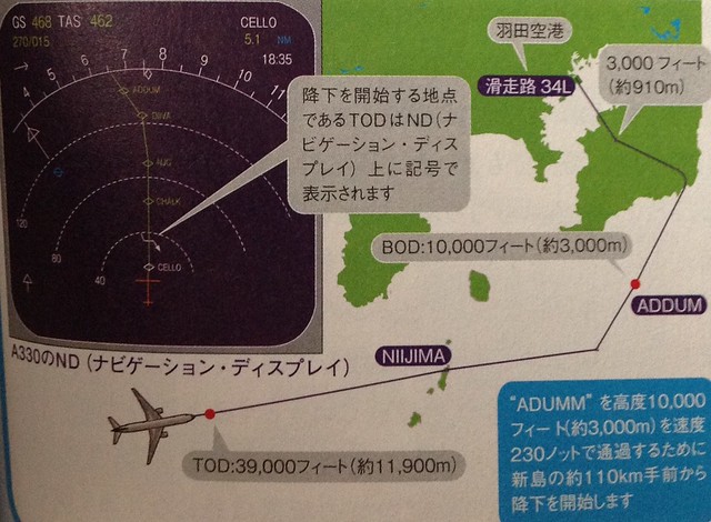 Generally, this point is called the Top of Descent (TOD) or T/D for short. It can be seen on the Navigation Display (ND) in map mode. In the Airbus 330 image above, it is represented by a bent arrow, located between the CELLO and CHALK fixes. Additionally, the start of the arrival is referred to as the Bottom of Descent (BOD).
For instance, in the Boeing 777’s ND, the location of T/D is directly marked by a dot on the flight path.
Generally, this point is called the Top of Descent (TOD) or T/D for short. It can be seen on the Navigation Display (ND) in map mode. In the Airbus 330 image above, it is represented by a bent arrow, located between the CELLO and CHALK fixes. Additionally, the start of the arrival is referred to as the Bottom of Descent (BOD).
For instance, in the Boeing 777’s ND, the location of T/D is directly marked by a dot on the flight path.
-
Exploring the Cockpit of an Airliner 5.4 Instrument Approach Charts
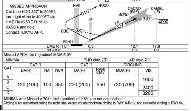
Let’s briefly summarize the instrument approach procedure using the approach chart, taking the ILS Z RWY34L (CAT II) procedure at Tokyo International Airport as an example.
Approach refers to the process of aligning the aircraft with the Runway during Descent. During the approach phase, the aircraft must adjust its altitude and align with the Runway to avoid ground obstacles. Pilots must maintain high concentration to operate accurately; therefore, approaches have strict standards and operating procedures. The “ILS Z RWY34L (CAT II)” mentioned above refers to the first (Z, with the second named Y and the third named X) instrument approach procedure name when entering Runway 34L at Tokyo International Airport.
-
Airliner Cockpit Secrets 5.3 Standard Instrument Arrival Procedures
The approach briefing dialogue discussed in the previous section was based on radar vectoring. Generally, when traffic volume is high, air traffic control (ATC) issues specific headings, altitudes, and speeds to each aircraft to maintain safe separation between flights; this is known as radar vectoring.
However, when traffic volume is low, Standard Instrument Arrivals (STARs) are often used. A STAR provides a method for an aircraft to transition from the en route phase to the terminal area flight. Generally, a STAR terminates at the Initial Approach Fix (IAF). The benefit of using a STAR is that it graphically depicts the arrival route structure and simplifies communication between ATC and pilots, eliminating verbose arrival instructions.
-
Airliner Cockpit Exploration 5.2 Approach Briefing
“The approach briefing is a statement by the pilot flying to the other pilot before a certain phase or maneuver of flight, outlining the intended implementation. It is a brief review of normal and non-normal procedures, control techniques, notes, and crew coordination for a specific action. This ensures crew members are clear on their responsibilities—how to handle normal situations and how to coordinate during abnormal ones—much like a pre-war rehearsal.
-
Airliner Cockpit Secrets 5.1 Descent Preparation
As the aircraft continues to approach the destination airport, the Captain and the First Officer must begin preparing for the Descent.
Generally, Descent preparation and the Approach/Go-around Briefing should be completed within 10 minutes prior to the Top of Descent (TOD) to avoid missing the optimal timing to begin the descent.
First, it is necessary to understand information regarding the destination. If local weather conditions are severe, such as a typhoon making landing impossible, or if an earthquake has just occurred making it impossible to ensure the safety of the airport Runway, the crew must consider diverting to an Alternate Airport.
-
Exploring Airliner Flying 4.9 Inside the Cockpit
Once the aircraft enters the cruise phase, although the pilot must still continuously monitor various flight data, the atmosphere in the cockpit is certainly more relaxed than during the takeoff phase. Before reaching the next checkpoint, the pilot can use the short break time to eat, get some drinks, use the bathroom, or just chat.
One thing to know about pilot food is that the Captain and the First Officer are absolutely not allowed to eat the same type of in-flight meal. This is mainly to prevent a situation where, in the event of an accident like food poisoning, both pilots cannot continue to perform the flying duties. Of course, there is generally no problem with the quality of the in-flight meals provided by airlines nowadays, but this rule is strictly enforced for safety reasons. Therefore, when a flight attendant comes to the cockpit to ask the pilots, for example, if today’s in-flight meals are Chinese and Western, if the Captain decides to order the Chinese meal, then the First Officer automatically gets the Western meal.
-
Exploring the Cockpit of Airliners 4.8: Weather and Turbulence (Continued)
In the previous section, when explaining the causes of turbulence, I didn’t mention Cumulonimbus clouds, so I’d like to add a supplement here.
 Cumulonimbus clouds are visually spectacular and very attractive as a natural landscape, but for an aircraft, flying into a Cumulonimbus cloud is a very dangerous matter. This is because there are very strong updrafts and downdrafts interacting within Cumulonimbus clouds, and their energy can cause huge damage to the aircraft body or even lead to the disaster of hull loss and fatalities. Even without flying into the Cumulonimbus, just flying over the cloud layer or passing by the side can cause severe turbulence that injures passengers. In addition, hail in the clouds and lightning near the cloud layer can also cause damage to the aircraft body.
Pilots mainly use weather radar to avoid Cumulonimbus clouds. However, if they encounter a giant high wall standing in front of the airway, it is impossible to adopt the method of significantly changing the route introduced in the previous section. Therefore, the pilot will turn on the cabin seatbelt sign, requiring passengers and flight attendants to sit tight in their seats. At this time, the pilot mainly uses manual control, concentrating on finding gaps in the clouds, weaving left and right, trying to find airspace with less turbulence, until passing through the cloud area. Sometimes, after a struggle, the pilot safely passes through the cloud area without any turbulence inside. Conversely, passengers unaware of the inside story might complain, “You made us sit still in our seats, but it didn’t shake at all,” as if the pilot’s prediction was inaccurate. Little do they know that this is the result of the pilot’s hard work; everyone, please do not misunderstand.
-
Airliner Cockpit Secrets 4.6 About Fuel Consumption and Center of Gravity
As previously introduced, in autopilot navigation mode, the aircraft automatically flies along the pre-set route, but pilots cannot be idle. They must constantly monitor flight instruments and record the passing time and remaining fuel quantity after passing each waypoint.
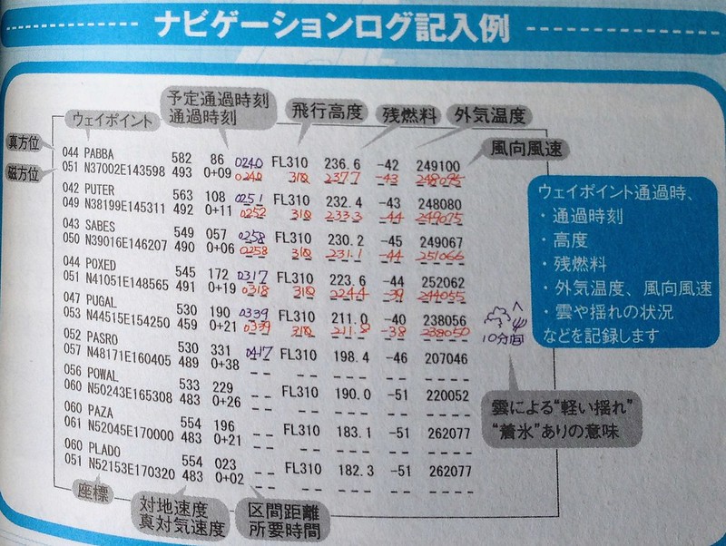 The above is an example of a flight log. You can see that for each waypoint, pilots record the passing time, flight altitude, remaining fuel, outside temperature, and wind direction/speed information. In the fifth line, information about 10 minutes of light turbulence during the journey is also recorded.
In this series 1.3 Flight Preparation Briefing, detailed flight planning was introduced. This plan is calculated based on the following information:
-
Inside the Cockpit 4.6 - Fuel Consumption and Center of Gravity
Previously, we introduced that in autopilot mode, the aircraft will automatically fly along a pre-set route. However, pilots cannot just sit idle; they must constantly monitor the flight instruments and record the passage time and remaining fuel quantity after passing each waypoint.
Above is an example of a flight log. You can see that for each waypoint, the pilot recorded the time of passage, flight altitude, remaining fuel, outside temperature, and wind direction/speed information. In the fifth line, information about 10 minutes of light Turbulence encountered during the journey is also noted.
In this series 1.3 Flight Preparation Briefing, a detailed flight plan was introduced. This plan is calculated based on the following information: Aircraft weight (calculated from the number of reserved passengers) Flight distance Flight speed High-altitude wind direction and speed forecasts High-altitude temperature