Aviation Knowledge Notes
-
Review of the E6-B Flight Computer
It's a typhoon day, I'm at home with nothing to do, so I took out my flight computer E6-B, which I haven't used in years, to brush up on it.

I couldn't remember how to use many of the functions, so I organized them on a Google spreadsheet to see if it would be easier to understand.

Function Calculation Content Outer Scale Outer Arrow/Mark Disc Arrow Inner Scale/Disc Scale 1 TimeRelationship between Speed, Flight Time, and Distance Distance 564nm - RATE points to outer scale Speed 125kt Time 4.5h 2 Fuel Consumption Fuel Amount 64gal - RATE points to outer scale Fuel Consumption Rate 8.4gal/h Flight Time 7h37m 3 Climb Rate Climb Rate 450ft/min - RATE points to outer scale Speed 90kt Climb Height per NM 300ft 4 Unit ConversionUnit Conversion NM - SM - KM - NAUT
STAT
KM- Nautical Miles 10
Statute Miles 11.5
Kilometers 18.55 Unit Conversion US Gal - Imp Gal - U.S. GAL
IMP. GAL- US Gallons 20
Imperial Gallons 16.66 Unit Conversion Weight - VolumeFuel Weight 192lbs FUEL LBS. U.S. GAL US Gallons 32 7 Oil Weight 90lbs OIL LBS. U.S. GAL US Gallons 12 8 Unit Conversion Lbs - KG 2000lbs LBS KG 901kg 9 Unit Conversion Liters - Gallons 50 Liters LITERS U.S. GAL 13.2 Gallons 10 Unit Conversion Feet - Meters 985ft FT METERS 300m 11 Unit Conversion TAS of Mach 1 TAS 660kt - PRESSURE ALTITUDE points to MACH NO INDEX, e.g. 15°C 1 Mach, fixed at10 12 Airspeed Correction Calculate TAS/Density Altitude based on IAS/Air Temp/Pressure Altitude
(Altimeter pressure setting adjusted to 29.92)TAS 183kt - Right side AIR TEMPERATURE -15°C
Right side PRESSURE ALTITUDE 10K
DENSITY ALTITUDE 15KIAS 145kt 13 Altitude Correction Calculate Field True Altitude MSL
※When outside air temperature is lower than standard atmospheric temperature (15.0°C), the altitude indicated will be higher than actual altitude
1. Adjust pressure setting to 29.92 to get Pressure Altitude (QNE)
2. Adjust pressure setting to Station QNH to get Corrected Altitude
3. Corrected Altitude - Field Elevation = AGL Uncorrected Height Diff
4. MSL = AGL Corrected Height Diff + Field ElevationAGL Corrected Height Diff 6600ft - Left side AIR TEMPERATURE -19°C
Left side PRESSURE ALTITUDE 10KAGL Uncorrected Height Diff 7000ft 14 Track Correction Track Correction Calculation
1. Calculate Drift Angle based on flown NM and current deviation distance
2. Calculate Drift Correction Angle based on remaining distance NM and current deviation distance
3. Total Correction = Drift Angle + Drift Correction Angle = 3.8 + 2.4 = 6.2°1 Deviation Distance 8nm
2 Deviation Distance 8nm- 1 RATE points to Drift Angle 3.8
2 RATE points to Drift Correction Angle 2.41 Flown NM 125
2 Remaining Distance NM 235 -
A Look at ACARS in Satellite Communication
An old article from ten years ago, A Chat About Methods for Personally Receiving ACARS Signals, introduced receiving VHF ACARS signals. I looked up some information on what ACARS over Satellite Communication (SATCOM) looks like.
First, looking at the Wikipedia page for the Malaysia Airlines MH377 disappearance event, the information regarding satellite communication is as follows:
Flight time 01:30 The Inmarsat-3 F1 satellite received the first of seven handshake signals Flight time 07:30 Inmarsat-3 F1 satellite captured the last complete handshake signal sent by the aircraft's ACARS, indicating it was still in flight Flight time 07:38 Unscheduled, via an unexplained "partial handshake" signal sent by the aircraft, the reserve fuel required after arrival in operational procedures should be running low Flight time 08:34 Inmarsat's scheduled next handshake time received no reply from the aircraft
Inmarsat is the International Maritime Satellite Organization. Similarly, via Wikipedia, you can see satellite services provided by Inmarsat:
 The coverage of the Inmarsat-3 F1 satellite is the Indian Ocean region. It was launched on April 3, 1996, and has been operating in space for 28 years.
 -
ANA's Pre-flight Walkaround Inspection Introduction Video
8 years ago, I blogged about Uncovering Airline Pilot Secrets 1.5: Pre-flight Ground Inspection, and I considered myself fairly knowledgeable about the process.
However, today I discovered a new series on the ANA (All Nippon Airways) website—
Thinking about what we could do as pilots during the STAY HOME period, we independently planned a video series: "The World of Blue Wings ~ Aviation Classroom at Home ~". The first installment delivers the Exterior Aircraft Inspection Edition.
After watching it, I still found some new learning points.
-
ZBAD Daxing International Airport Charts
AIP China has publicly released the charts for ZBAD Daxing International Airport. I immediately found them and took a look, and have placed them in the China Charts - Daxing Airport page on this site for your reference.

From the chart, you can see that Daxing Airport has a total of 4 Runways: 17R/35L and 17L/35R in the north-south direction, as well as 19R/01L, and 11L/29R in the east-west direction. Except for Runway 19R/01L, which is 3400 meters long, the other three Runways are all 3800 meters long. Regarding Runway width, except for 17R/35L which is 45 meters wide, the others are all 60 meters wide. You can see on the left side of the chart that there is another Runway under construction; I don’t know what its designation will be.
-
A Simple Note on Max Motoring
Max Motoring
“Cold motoring” refers to the state where the aircraft engine operates without ignition or starting, powered solely by the electric motor. “Max motoring speed” refers to the maximum speed allowed for the engine in this state.
For specific applications, please refer to the description of the Boeing 737 engine start procedure on b737.org.uk.
Min 25% N2 (or 20% N2 at max motoring) to introduce fuel; any sooner could result in a hot start. Max motoring is when N2 does not increase by more than 1% in 5 seconds.
-
China Eastern Flight Training Materials: Flight Management Series Lecture Hall
I came across some extremely professional materials on WeChat, so I simply had to share them here for everyone to learn from together.
Flight Management Series Lecture Flight Management Series Lecture (Continued)
Special thanks to the instructor, Mr. Zhou Xiaoqing, from the Flight Technique Management Department of Shanghai Eastern Flight Training Co., Ltd., China Eastern Airlines.
Lecture 1 — Flight Elements
Lecture 2 — Aircraft
Lecture 3 — Control
-
Observing Details of Various Intake and Exhaust Vents on the Boeing 737-800 Tail
I was looking back at photos from last week at Haneda Airport and noticed there are many small openings on the tail of the Boeing 737-800, and I didn’t know what most of them were for.
 So I marked them with small circles in the photo and consulted an expert, Mr. @dreamliner, and got the following answers.
1 Tail White Position Light Strobe Light 2 APU Compartment/Oil Cooling Air Inlet APU Cooling Air Inlet 3 APU Exhaust Outlet APU Exhaust Outlet 4 APU Access Panel 5 APU Compartment Combustible Liquid Drain 6 APU Compartment Combustible/Non-combustible Liquid Drain APU Shroud & Hydraulic Drain 7 Green Tail Skid, preventing tail strikes Tail Skid 8 APU Air Inlet APU Air Inlet Door 9 Aft Galley/Lavatory Waste Water Drain Mast Aft Heated Water Drain Mast 10 Galley Exhaust Outlet 11 Emergency Light (e.g., after emergency slide deployment) 12 Positive Pressure Relief Valve (Cabin pressurization emergency regulation, exhausts air from cabin, two in total. Not clearly visible in the photo, but there is actually another one below the outflow valve) Pressure Relief Valves 13 Outflow Valve (Cabin pressurization regulation) Outflow Valve 14 Negative Pressure Relief Valve (Cabin pressurization emergency regulation, draws air into cabin from outside) Negative Pressure Relief Valve
-
GUMPS checklist
Pre-landing Mental Preparation Checklist: GUMPS, a simple note. G - Gas Fuel selector BOTH, Fuel pump ON, Proper fuel pressure, etc. U - Undercarriage Landing gear down M - Mixture Fuel mixture RICH P - Propeller Propeller pitch high (coarse) S - Seat belts and Switches Seat belts, Lights, Pitot heat, etc. -
Anti-Servo Tab on Small Aircraft
Horizontal Stabilizer: Horizontal Stabilizer
Elevator: Elevator
Stabilator: Stabilator
Anti-Servo Tab: Anti-Servo TabThe Elevator is typically installed at the rear section of the Horizontal Stabilizer.
 The Horizontal Stabilizer is fixed, while the Elevator is movable.
However, for a Stabilator, the stabilator itself functions as the elevator.
Trim is still necessary, and this is often achieved by the movable section at the rear of the Stabilator
—the Anti-Servo Tab.<img src=http://image.slidesharecdn.com/aircraftbasics-140927035356-phpapp02/95/aircraft-basics-35-638.jpg?cb=1411790115>
-
Rich of Peak and Lean of Peak
I picked up some more knowledge from the experts on Baidu Tieba, so I’m sharing it below.
When you pull the mixture back, you will eventually reach a highest EGT value —- Peak. At this point, if you push the mixture forward a bit, it is called Rich of Peak. At this point, if you pull the mixture back a bit, it is called Lean of peak.
When you push forward a bit to reach a value slightly lower than the maximum EGT, you often obtain a maximum Thrust mixture ratio. For example, if the peak is 500 degrees and you push the mixture forward to reach 475 degrees where the Thrust is maximum, it is called 25 degree rich of peak.
-
What is the purpose of the static port on the vertical stabilizer?
This Star Alliance livery ANA Boeing 777 was shot at Tokyo Haneda Airport Terminal 2.

If you look closely at the Vertical Stabilizer, you can see two small white circles on the leading edge.
So, I zoomed in on the photo. Although it’s not very clear, you can still make out the text “Static Port” to the left of the circle,
-
Review of the ASA E6-B Flight Computer
Today is a holiday called “Culture Day”, and I’m resting at home. Recalling the discussion about flight computers during the LUXURY FLIGHT, I realized I’ve forgotten quite a bit about how to use them, so I decided to review the E6-B.
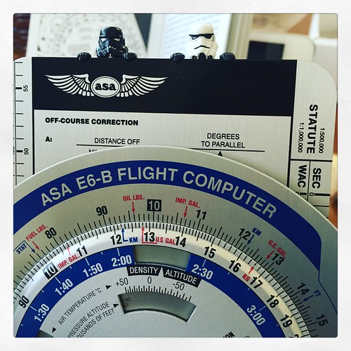
Specific usage instructions are available in this site’s repository, so I won’t go into detail here. <a href=https://yinlei.org/x-plane10/view1.php?file=doc/e6b-manual.pdf>Simplified Chinese version of ASA E6B Instructions English version of ASA E6B Instructions
-
Cost Index CI cost index
In visiting JFlight’s A320 BFPT flight simulator, it was mentioned that the Cost Index (CI) was set to 20 at the time. I wondered what this value typically is during actual flight, so I consulted two professionals. Their answers are as follows.
A Boeing 737 pilot told me it is generally at 35, and according to Cruise speed requirements, the higher the speed, the larger the CI. Senior L told me that their company’s narrow-body aircraft range from 20 to 50, while wide-body aircraft are slightly higher, and international routes are higher than domestic routes. Additionally, this value is calculated by the company’s operations department based on the relationship between fuel costs and time costs. When piloting, the flight crew enters this result into the FMC via the CDU (MCDU).
-
A320 Load Sheet
From time to time, you can see A320 landing load reports on SNS. There is a great article on CARNOC on how to read an A320 load report.
I particularly like the section on the cause of the overload. For instance, if a landing is too heavy, there is data for a second touchdown (touchdown), whereas the introduction above shows 0.
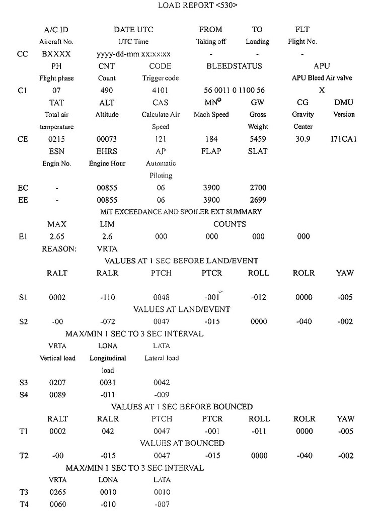 The information above is from a Google Patent page.
Explanation of Terms in the Cause Section
-
Visual Perspective Changes During the Flare
I won’t write out the specific procedures; the materials from the Federal Aviation Administration (<a href=https://www.faasafety.gov/gslac/ALC/course_content.aspx?cID=34&sID=164&preview=true>FAA) below are easy to understand:
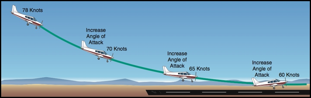
However, regarding how to observe the changes in the visual perspective of the Runway, the explanation by the <a href=http://tieba.baidu.com/p/3970321943?pid=73705731249>Beautiful Pilot is very good, so I have transcribed it here.
During the Roundout, it is generally believed that you should look at the far end of the Runway. This is because, when you focus on the distance, you can see more details, and all the surrounding scenery is "telling you" the sink rate and altitude.
When focusing on the distance, you actually need to pay attention to the area in front of and to the sides of the nose cowling as well. When looking far ahead, there will be a moment when you feel the Runway being “flattened” significantly; at the same time, when you scan the front and sides of the nose cowling, there will be a moment when you feel the Runway expanding significantly. That is when you should perform the Roundout.
-
Runway Overrun Prevention System ROPS
Regarding the news on Airbus’s Runway Overrun Prevention System (ROPS), the ROPS application for the A330 series aircraft has recently successfully obtained airworthiness certification from the European Aviation Safety Agency (EASA). 空客ROPS应用于A330获认证,ROPS覆盖空客全机型 A330のオーバーラン防止装置、EASAが認可
Here is a summary of the ROPS data. As explained in the article from the China Civil Aviation Network above, ROPS is essentially an alert system. It helps improve pilots’ situational awareness during landing, reduces the risk of aircraft overrunning the runway, and in necessary situations, the system can provide active protection for the aircraft. From now on, all Airbus aircraft models can have ROPS installed upon delivery, and all in-service Airbus aircraft can also be modified to install ROPS.
-
Coupled Approach
1 This actually refers to whether a specific aircraft can automatically follow the localizer and glideslope. General aviation in Europe frequently utilizes ILS and MLS, but many older aircraft may not have an autopilot capable of automatically following them.
2 An instrument approach performed by the aircraft autopilot, which is receiving position information and/or steering commands from onboard navigation equipment.
In general, coupled non-precision approaches must be discontinued and flown manually at altitudes lower than 50 ft below the minimum descent altitude, and coupled precision approaches must be flown manually below 50 ft AGL (above ground level).
-
Some Airway Updates
Mainland China <a href=/x-plane10/view.php?file=doc/IFRMFCNr1507.pdf>International Flight Routes from Mainland of China Nr1507 <a href=/x-plane10/view.php?file=doc/IFRTMCNr1507.pdf>International Flight Routes to Mainland of China Nr1507 <a href=/x-plane10/view.php?file=doc/OFRNr1507.pdf>Overflying Flight Routes Nr1507 <a href=/x-plane10/view.php?file=doc/RFRNr1507.pdf>Regional Flight Routes Nr1507
Japan <a href=https://yinlei.org/x-plane10/view.php?file=doc/JP-eAIC-2015-032-en-JP.pdf>Flight Planning Routes 20 AUG 2015 Flight Planning Routes 30 APR 2015
United States NFDC Preferred Routes Database Query NFDC Preferred Routes Database
-
ATC Surveillance Minimum Altitude Chart
Reading the AIP (Aeronautical Information Publication) out of boredom, I noticed a new type of chart added in the China Civil Aviation eAIP — the ATC Surveillance Minimum Altitude Chart. Since this was a new piece of knowledge for me, I decided to look it up.
Here is the ICAO explanation for the ATC Surveillance Minimum Altitude Chart:
This supplementary chart must provide information which will enable flight crews to monitor and cross-check altitudes assigned while under radar control by a controller using an ATS surveillance system.
-
ILS Magnetic Bearing Can Also Change
Check the information <a href=http://dgraph.info/air/?itemid=414>here; the magnetic bearing of the ILS localizer course has changed. Starting from June 25, it changed from 79 degrees to 80 degrees. Is this phenomenon common? Is it caused by changes in magnetic variation?
I would appreciate expert advice.
Wakkanai Airport ILS-LOC 08 Magnetic Bearing Change
(1) ILS-LOC 08: 111.1MHz [IWK] CAT-I opr0830~1830
(2) ILS-LOC 08 BRG(MAG): 079 → 080
(3) Effective Date: 15/06/25
