Airliner Cockpit Secrets 5.5 Initiating Descent
In Section 5.3, when summarizing the Standard Instrument Arrival Procedure, it was mentioned that based on the position and altitude information of the initial arrival waypoint, and by referencing the Estimated Time of Arrival (ETA), fuel consumption rate, engine performance, and wind direction/speed, the pilot can configure the engine parameters and descent rate for the descent phase.
For example, the KAIHO arrival procedure starts at the ADDUM waypoint located in the Pacific Ocean, with a minimum enroute altitude of 10,000 feet. To descend from cruise altitude to ADDUM, the Flight Management Computer (FMS) calculates that the aircraft needs to begin descending from a point 200 kilometers west of ADDUM.
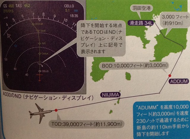 Generally, this point is called the Top of Descent (TOD) or T/D for short. It can be seen on the Navigation Display (ND) in map mode. In the Airbus 330 image above, it is represented by a bent arrow, located between the CELLO and CHALK fixes. Additionally, the start of the arrival is referred to as the Bottom of Descent (BOD).
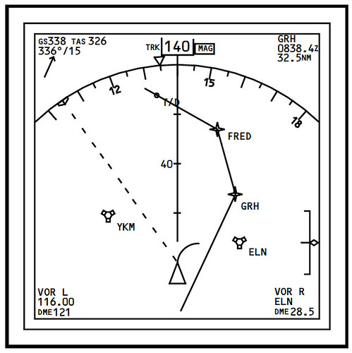
For instance, in the Boeing 777’s ND, the location of T/D is directly marked by a dot on the flight path.
Generally, this point is called the Top of Descent (TOD) or T/D for short. It can be seen on the Navigation Display (ND) in map mode. In the Airbus 330 image above, it is represented by a bent arrow, located between the CELLO and CHALK fixes. Additionally, the start of the arrival is referred to as the Bottom of Descent (BOD).
For instance, in the Boeing 777’s ND, the location of T/D is directly marked by a dot on the flight path.
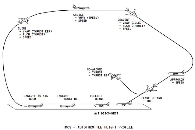
After passing TOD, the aircraft begins its automatic descent. The diagram below illustrates the entire flight profile. (This diagram primarily explains the Autothrottle modes during each flight phase, but it is also suitable for explaining the descent process, so I am borrowing it here.)
Regarding the descent process, one crucial point to understand is that an aircraft does not reduce altitude merely by pushing the elevators down (i.e., lowering the nose); rather, the descent angle is controlled by the throttle.
When transitioning from Level Flight to a Descent, the pilot reduces the throttle appropriately, which causes the aircraft to decrease speed. Since lift is directly proportional to speed, a reduction in speed results in a reduction in lift. Consequently, lift becomes less than gravity, and the aircraft begins to descend. During the descent, the flight path is no longer horizontal but tilts downward at an angle. At this point, the aircraft’s pitch attitude hasn’t changed, but its direction of motion has shifted from straight ahead to slightly downward. This increases the Angle of Attack, which in turn increases lift. This additional lift balances the component of gravity along the flight path, restoring equilibrium among all external forces, and the aircraft enters a state of uniform descent.
During the descent, the aircraft’s nose pitches down. This attitude requires very little thrust; often, the throttle can be fully closed to glide. You may have noticed that the cabin becomes very quiet at the beginning of a descent when flying as a passenger. You can imagine the aircraft’s attitude during descent as a car coasting downhill: without stepping on the gas, the car descends steadily. A steeper slope results in higher speed, while a gentler slope results in a lower speed. The Flight Management Computer (FMC) on modern aircraft can automatically adjust the throttle and attitude effectively according to the pilot’s requirements.
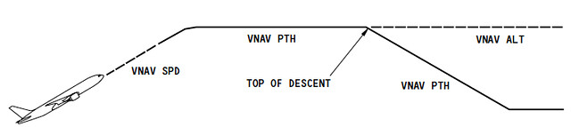
Generally, pilots can select between two descent modes: maintaining a constant speed or maintaining a specific flight path angle. This corresponds to the FMC pitch settings, allowing the selection of either VNAV SPD (Vertical Navigation Speed Mode) or VNAV PTH (Vertical Navigation Path Mode).
During a VNAV SPD descent, the autothrottle system typically maintains an idle state, while the Auto Flight Director System (AFDS) controls the aircraft to maintain the target speed set in the FMC.
During a VNAV PTH descent, the FMC generally controls the aircraft to maintain a 3-degree descent angle, with the computer automatically controlling the speed between TOD and BOD. For example, if wind causes the aircraft to deviate upwards from the 3-degree path, the FMC will increase speed to force the aircraft back onto the original path.
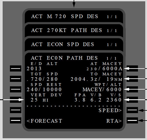 The image above shows the CDU of a Boeing 737 in VNAV PTH mode. At the start of the descent, the mode changes from the cruise ACT ECON CRZ to ACT ECON PATH DES. Line 2L displays the current speed as Mach 0.72 / 280 knots, while line 3L displays the speed restriction. Since industry regulations limit speed to 250 knots below 10,000 feet, the speed restriction is specifically set to 240 knots to ensure compliance.
Why is a 3-degree angle generally adopted for descent? This is because a 3-degree angle facilitates mental calculation of the relationship between altitude and descent distance. You can easily estimate this using the following approximate formula: Descent Distance Required (NM) = Flight Altitude (ft) / 1000 * 3
For example, descending from a cruise altitude of 33,000 feet to ground level: 33000 / 1000 * 3 yields 99 nautical miles (approximately 190 km). Therefore, for an aircraft to descend from 33,000 feet (or 10 km), the descent must commence at least 190 km from the destination airport.
Prev: Standard Instrument Arrival Procedure TOC: Table of Contents Next: ATC Communication during Descent