Airliner Cockpit Exploration 3.7 ATC Handoff to Center, Continue Climb
First, let’s take Air System Flight 115 from Tokyo Haneda Airport to Hokkaido Sapporo New Chitose Airport as an example again. Let’s look at the Air Traffic Control (ATC) process required for this flight from takeoff to cruise and landing:
1 Haneda Airport: Delivery Control — Ground Control — Tower Control — Departure Control 2 Area Control: Tokyo Control Area — Sapporo Control Area 3 New Chitose Airport: Approach Control — Tower Control — Ground Control
The aircraft is constantly handed over to different units between airport control and area control, ensuring flight safety in each segment like a relay race, as shown in the two figures below.
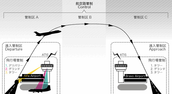 The left side shows the Delivery, Ground, Tower, and Departure control at the departure airport.
The right side shows the Approach, Tower, and Ground control at the destination airport.
The left side shows the Delivery, Ground, Tower, and Departure control at the departure airport.
The right side shows the Approach, Tower, and Ground control at the destination airport.
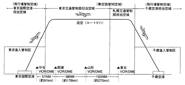 Diagram of the aircraft's flight altitude and the corresponding control areas.
Below is a partial introduction to Japan’s area control regions. You can see that each control region is actually divided into several smaller control sectors.
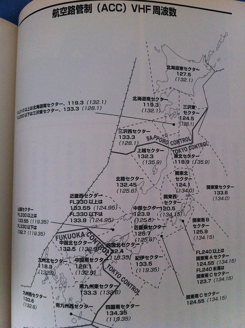 For example, this flight needs to pass through the Kanto West Sector and Kanto East Sector within the Tokyo Control Area, and the Tohoku Sector,
as well as the Misawa East Sector and Hokkaido East Sector within the Sapporo Control Area. It takes a total of 5 sector relays to finally enter the Sapporo Airport control area.
For example, this flight needs to pass through the Kanto West Sector and Kanto East Sector within the Tokyo Control Area, and the Tohoku Sector,
as well as the Misawa East Sector and Hokkaido East Sector within the Sapporo Control Area. It takes a total of 5 sector relays to finally enter the Sapporo Airport control area.
Air System Flight 115 is continuously climbing towards the Moriya Waypoint. Haneda Departure Control begins to instruct the pilot to contact Tokyo Control: “Air System 115, Contact Tokyo Control 124.1, Good day.” This means: “Air System 115, Contact Tokyo North Kanto Area Control Center 124.1, Good day.” The First Officer repeats back: “Tokyo 124.1, Air System 115, Good day.” Then, tune the communication radio frequency to Departure Control 124.100 MHz and contact: “Tokyo Control, Air System 115, Leaving 7800 for FL210, Initially Proposed FL410.” This means: “Tokyo Control, Air System 115 here, passing through altitude 7800 feet for 21000 feet, final target altitude 41000 feet.” The Tokyo North Kanto Controller confirms the handoff and issues the following instruction: “Air System 115, Tokyo Control, Roger. Cancel Restriction, Climb and Maintain FL410.” This means: “Air System 115, Tokyo Control here. Roger. Cancel climb speed restriction, Climb and Maintain FL410.” The First Officer continues to read back the instruction: “Cancel Restriction, Climb and Maintain FL410, Air System 115.” That is: “Cancel restriction, Climb and Maintain FL410, Air System 115.”
The airflow during the climb is smooth, and looking from the cockpit, there are no cloud systems ahead that would cause air turbulence, so the “Fasten Seatbelt” sign can be turned off. The Captain instructs the First Officer, “Fasten Belts Switch Auto.” This switch is generally located on the overhead panel. After the First Officer moves the switch from the ON position to the AUTO position, a “ding” sound is heard in the cabin. At the same time, the seatbelt sign on each seat goes off. Flight attendants stand up from their seats to start preparing drinks and food for passenger service. The slightly tense atmosphere in the cabin immediately relaxes. Passengers can put down their tray tables, adjust their seat backs, and in-flight movies and other entertainment systems begin.
When the “Fasten Belts Switch” is in the AUTO position, as long as both the landing gear and flaps are retracted, the “Fasten Seatbelt” sign in the cabin will remain off. However, if either the landing gear or flaps are extended, the sign will automatically illuminate. During flight, if there are no unstable weather conditions like air turbulence, pilots will turn on this switch as early as possible, giving flight attendants ample time to prepare for passenger service.
Using airborne weather radar, pilots can grasp cloud conditions as early as possible, and sometimes fly around turbulent areas that might bring turbulence. But if they encounter unexpected Clear Air Turbulence (CAT), pilots can turn on the seatbelt switch at any time, reminding everyone to fasten their seatbelts to ensure the safety of passengers and crew.
After the aircraft altitude exceeds 10,000 feet, the pilots turn off the landing lights. As introduced in Section 2.7 (Takeoff Clearance), these are the large lights located under the left and right wings to prevent collisions. Regulations require these lights to be ON from takeoff until reaching 10,000 feet.
Additionally, there are no speed limits anymore. The FMC (Flight Management Computer) controls the aircraft to continuously accelerate at the economic climb speed. The horizontal stabilizer trim control wheel located near the throttle automatically rotates forward, decreasing the climb angle of attack, and the nose moves down.
It is important to know here that the means of controlling airspeed during the climb and cruise phases is not the throttle; the throttle setting is basically fixed here. The FMC calculates the economic climb speed and sends the data to the Autoflight Director System (AFDS). The AFDS maintains the aircraft speed at the economic speed by adjusting the pitch angle of the nose.
The aircraft altitude continues to rise, quickly exceeding 14,000 feet. In Japan, after exceeding 14,000 feet, pilots need to set the Altimeter standard from the corrected sea level pressure (QNH) to the standard atmospheric pressure (QNE). This altitude is called the Transition Altitude. (It seems China also regulates this at 14,000 feet, while the US regulation is 18,000 feet)
Under standard atmospheric conditions, the ratios of air pressure, temperature, and air density are determined by altitude. Knowing these values means knowing the altitude. From this, pressure altitude, temperature altitude, and density altitude can be derived. Among these three, temperature and air density vary too much to be used for determining altitude, so aircraft generally use pressure altitude. Pressure variations can be corrected to obtain the correct altitude (altitude above sea level); this correction value is called QNH. QNH is the sea level pressure at the current location. An Altimeter corrected by QNH indicates the correct altitude when the temperature is in a standard atmospheric state, but when the temperature is in a non-standard state, the obtained altitude will differ from the actual altitude. All aircraft, through QNH correction based on their location, can maintain appropriate separation (altitude difference), and can indicate the airport elevation when at the airport.
The so-called pressure altitude QNE is the altitude indicated by the barometer when QNH corresponds to the standard atmospheric state (1013.2 hPa). The altitude indicated by the QNH-corrected Altimeter is called Indicated Altitude. When flying below 14,000 feet, the altitude is set according to QNH. When flying above 14,000 feet, fly according to QNE; this flight altitude is called a Flight Level (FL). The altitude of 14,000 feet is called FL140, omitting the last two digits. So looking back at the ATC dialogue above, you can see that for 21,000 feet, FL210 is used, while for 7,000 feet, 7000 is used directly.
Also note that the Captain and First Officer must not only set their own Altimeters and the standby Altimeter to 2992, but also cross-check to ensure both sets of data are correct.
The aircraft continues to climb at high speed and is soon approaching the cruising altitude.
Prev: ATC Handoff to Departure, Entering VNAV Mode TOC: Table of Contents Next: Entering Level Cruise
End