Title: Unveiling Airliner Cockpit Secrets 3.6 ATC Handover to Departure Control, Entering VNAV Mode
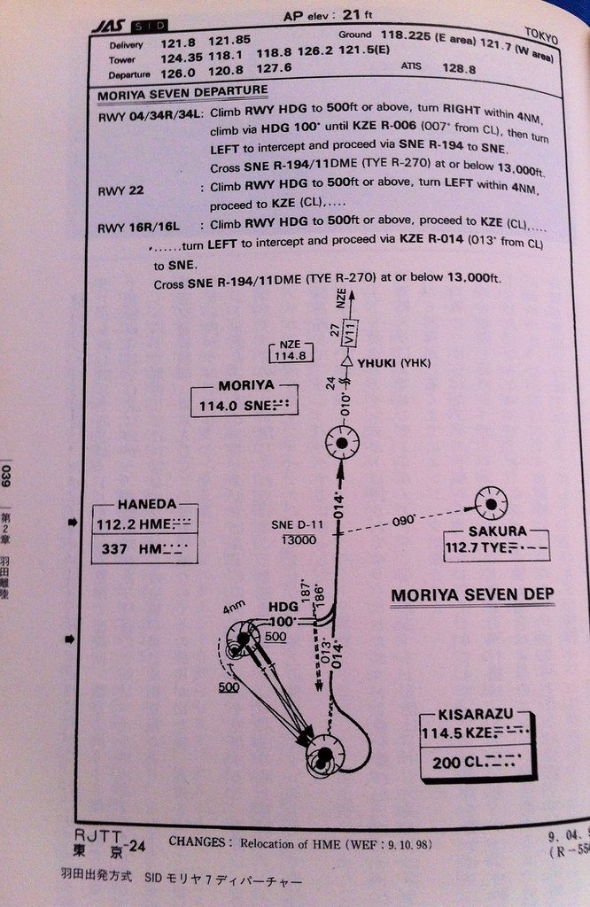
Taking AirSystem Flight 115 as an example, the aircraft follows the Moriya 7 Departure procedure at Haneda Airport. It first flies along the Runway (16R) direction to the KZE (KISARAZU) waypoint at the bottom right of the chart, then automatically banks left 30 degrees, turning to a 14-degree direction (basically close to due north) to fly towards the SNE (MORIYA) waypoint.
At this point, after the Tower controller confirms the aircraft’s departure is correct, they instruct the pilot to contact Departure Control: “Air System 115, Contact Departure” This means “Air System 115, contact Tokyo Departure” The First Officer replies “Departure, Air System 115” Meaning “Contacting Tokyo Departure, Air System 115” Then, tunes the radio frequency to Departure Control 120.800MHz, and calls: “Tokyo Departure, Air System 115, Leaving 1800” This means “Tokyo Departure, this is Air System 115, passing through 1800 feet” The controller replies “Air System 115, Tokyo Departure, Radar Contact, Turn Left Heading 020, Vector to Moriya, Climb and Maintain 210” This means “Air System 115, this is Tokyo Departure, radar contact, turn left heading 020, radar vector to Moriya, Climb and Maintain 21000 feet” The First Officer reads back: “Left 020, Direct 210, Air System 115” Meaning “Turn left heading 020, maintain 21000 feet, Air System 115”.
According to the standard departure procedure above, we know there is an altitude restriction 11 miles ahead of MORIYA, meaning flight must be kept below 13000 feet (approximately 3300 meters). However, here the Departure controller allows the pilot to bypass the KZE waypoint, turn directly towards MORIYA and climb directly to 21000 feet, perhaps because traffic is light today. For the airline, this saves both time and fuel, which is excellent. Therefore, the pilot turns the Heading Selector knob on the MCP to 020.
Now the aircraft’s speed is in MCP SPD mode, so the pilot needs to continuously increase the speed target and retract the deployed Flaps.
For example, taking the 737-500 mentioned earlier, if the takeoff Flaps setting is 5, the pilot can first retract them to 1 degree, Flap 1.
The speed condition for Flap 1 is V2+15 knots or above, and the current climb speed has reached V2+20 knots, so retracting to 1 is fine.
At the same time, the after-takeoff procedure begins: the Auto Brake switch is moved from RTO to OFF,
 The Landing Gear lever is also moved to the middle OFF position (from top to bottom: UP/OFF/ON), and the Engine Start switches are moved from CONT to OFF.
As speed continues to increase, fully retracting the flaps is no problem. The maneuvering speed for the 737-500 with Flaps UP is 210 knots. Around 190 knots, the Captain instructs the First Officer “Flap UP”, fully retracting the leading and trailing edge flaps into the wings, placing the aircraft in a state of minimum Drag.
The Landing Gear lever is also moved to the middle OFF position (from top to bottom: UP/OFF/ON), and the Engine Start switches are moved from CONT to OFF.
As speed continues to increase, fully retracting the flaps is no problem. The maneuvering speed for the 737-500 with Flaps UP is 210 knots. Around 190 knots, the Captain instructs the First Officer “Flap UP”, fully retracting the leading and trailing edge flaps into the wings, placing the aircraft in a state of minimum Drag.
The Captain increases the speed to 250 knots on the MCP again and instructs the First Officer on the After Takeoff Checklist,
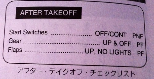 Checking items such as Engine Start switches off, Landing Gear up, and Flaps up.
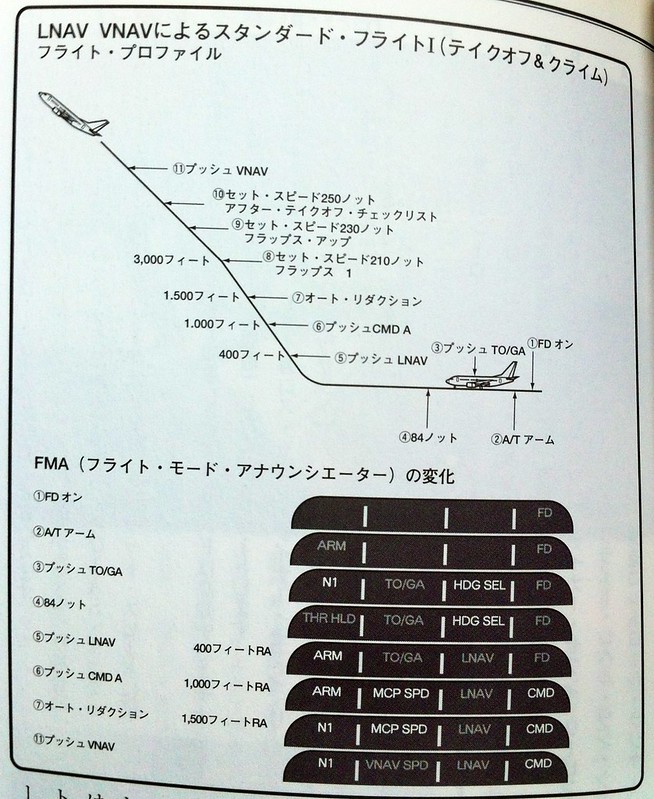
After the check, the Captain initiates VNAV mode. VNAV is short for Vertical Navigation. The FMC (Flight Management Computer) calculates the vertical Climb, Level Flight, and Descent speeds based on the aircraft’s optimal economic speed (ECON SPD), and displays them on the FD. The optimal economic speed refers to the most economical flight speed considering the relationship between flight time and fuel consumption. Generally, faster speeds mean shorter flight times but higher fuel consumption; slower speeds save fuel but take longer. The computer calculates a speed from various combinations of speed and fuel consumption that saves both fuel and time per unit time, and uses this speed for Climb, Cruise, and Descent. Modern jet airliners have powerful engines, generally achieving a Climb rate of 700-800 meters per minute, so reaching a cruising altitude of 10,000 meters from takeoff only takes about 15 minutes.
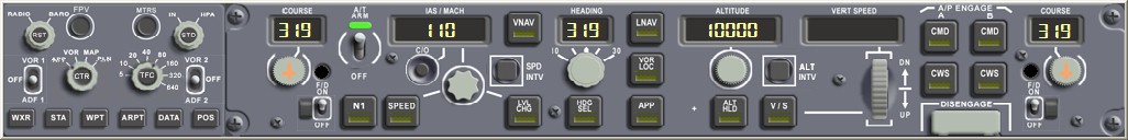
After pressing the VNAV key, the pitch setting in the upper left mode bar on the PFD changes from MCP SPD to green VNAV SPD, and the flight mode enters Phase 11 in the diagram below.
 At this time, the numbers in the IAS/MACH window on the MCP also disappear, and the aircraft’s speed is completely under FMC control.
If, for certain reasons, such as Air Traffic Control adjusting separation between aircraft requiring the pilot to adjust speed, You can press the SPD INTV (Speed Intervention) key below the VNAV key. This allows IAS/MACH to be activated even in VNAV mode, Enabling the pilot to input a temporary speed to fly at the speed specified by IAS/MACH.
Once the temporary speed adjustment is complete, the pilot can press the SPD INTV key again; the IAS/MACH display disappears, And the aircraft speed is once again controlled by the Flight Management Computer (FMC).
Prev: Engaging Autopilot TOC: Table of Contents Next: Transfer to Center Control, Continue Climb
End