Title: Airliner Cockpit Secrets 3.3 Takeoff and Liftoff
As the aircraft’s speed continues to increase, a green arrow known as the speed trend vector will appear on the speed strip on the left side of the PFD.
 It indicates the current acceleration of the aircraft; the arrow pointing up shows the aircraft is accelerating, while down indicates deceleration.
The speed pointed to by the arrow is the predicted aircraft speed value 10 seconds in the future.
By observing the speed trend vector, the pilot can know the future speed trend of the aircraft, which is particularly helpful for control during the Takeoff and Departure phases.
It indicates the current acceleration of the aircraft; the arrow pointing up shows the aircraft is accelerating, while down indicates deceleration.
The speed pointed to by the arrow is the predicted aircraft speed value 10 seconds in the future.
By observing the speed trend vector, the pilot can know the future speed trend of the aircraft, which is particularly helpful for control during the Takeoff and Departure phases.
After the aircraft speed exceeds 45 knots, you can see the speed trend arrow rising rapidly; the aircraft speed gets faster and faster, and the acceleration reaches its maximum value when the speed reaches V1.
Since the aircraft is in FD (Flight Director) mode, a purple FD command bar will appear above the aircraft’s own symbol in the center of the PFD.
It indicates the attitude the aircraft should currently be in, as calculated by the flight computer to reach the set speed, altitude, and Heading according to the route.
The pilot should follow the display of the FD command bar, controlling the yoke or sidestick to pitch up or down or bank left or right, to align the aircraft with the command bar, and the aircraft will faithfully fly according to the flight plan.
The diagram below shows the PFD display of a Boeing 737; the purple symbol resembling an inverted ‘V’ is the FD command bar (flight director command bar), and the white inverted ‘V’ symbol below represents the pilot’s own aircraft. In the image below, the aircraft needs to perform a pull up +8 degrees nose-up operation.
 On Airbus aircraft, the display is as shown below: the Flight Path Director (FPD) line is the command given by the computer, and the Flight Path Vector (FPV) indicates the aircraft’s orientation. The pilot must control the aircraft to place the FPV in the center of the FPD.
 You might perhaps feel that flying a plane is a bit like playing a video game? Of course, things aren’t that simple. Due to failures of various sensors or systems, the computer may issue incorrect commands, so pilots must constantly monitor various instruments and check whether the commands issued by the computer are correct, rather than blindly executing computer commands without analysis.
During the taxiing phase, the computer’s pitch indication will stay at the -10 degrees level position, and when the speed reaches 60 knots, the FD command bar moves to the +15 degrees position, but since Vr has not yet been reached, the control column must not be pulled back to raise the nose yet.
After the speed reaches 80 knots, the First Officer, who has been observing the instruments, will call out “80”, while the Captain must still press the yoke forward lightly with the left hand and control the rudder pedals with both feet to keep the aircraft taxiing on the runway centerline. Through the rudder pedals, the nose wheel can be steered left and right by 7 degrees (data for Boeing 737), so using the rudder pedals is sufficient for fine directional adjustments during takeoff and landing. On the ground, the computer cannot yet give horizontal commands, so the Captain must visually look at the outside runway centerline, observe whether the current aircraft is deviating, and constantly adjust the direction.
After the ground speed reaches 84 knots, the mode display on the PFD will change to “THR HLD, TO/GA, HDG SEL” (Item 4 in the image below).
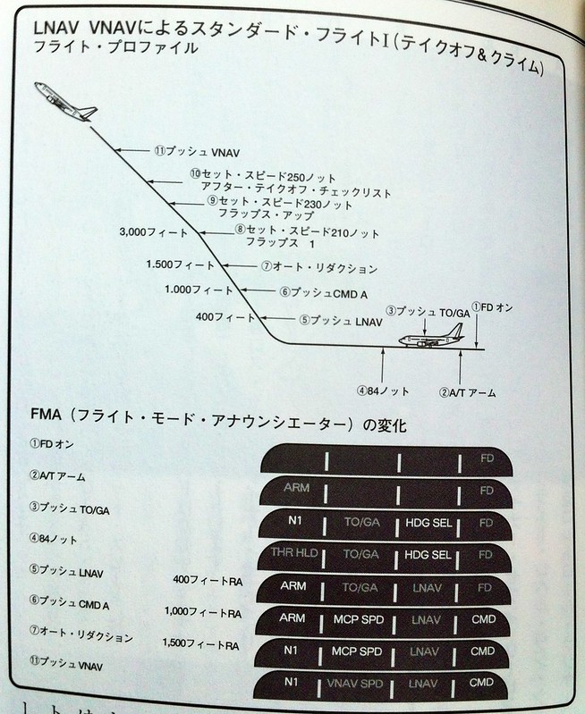 THR HLD indicates that the engine autothrust value is locked; the engine will continue flying with this throttle thrust until the aircraft is 18 seconds off the ground or reaches an altitude of 400 feet, after which changing thrust is permitted. THR HLD ensures that during the Takeoff phase, the engine will not suddenly reduce throttle due to special reasons, guaranteeing the safety of the aircraft.
The aircraft continues to accelerate to reach the takeoff decision speed V1, and the First Officer continues to call out “V1”. It is said that the pronunciation rule is to start speaking when the speed display is 5 knots away from V1, and finish speaking the “1” exactly when the speed display shows V1. After reaching V1, the aircraft must not stop even if a malfunction occurs; the takeoff action must be completed. Therefore, after hearing the First Officer’s report, the Captain must move the right hand, which has been resting on the engine thrust levers, to the yoke to start flying the takeoff with both hands, or place it on the armrest. (Before this, the Captain must be ready to stop the engine at any moment in case of an accident, so the right hand stays on the thrust levers. After V1, moving the right hand away can improve safety to prevent incorrect throttle operation.)
Immediately after, the rotate speed Vr arrives. The First Officer continues to call out “Vr”. The Captain is actually staring at the instruments at this moment and does not wait for the First Officer’s report to operate; instead, at the instant the aircraft reaches the Vr speed—which is the same time the First Officer calls “Vr"—pull back the control yoke to raise the nose at a rate of approximately 3 degrees per second, rotating the aircraft to the +15 degrees position of the FD command bar on the PFD. Since the timing of this action has a significant impact on the takeoff roll distance, a slight delay increases the ground roll distance, so the pilot’s operation must be performed as simultaneously with Vr as possible.
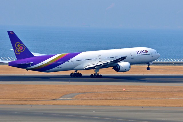 The moment the nose gear of a Thai Airways Boeing 777 lifts off the ground. The image above was taken by me at Chubu Centrair International Airport in Nagoya, Japan.
I once asked on Weibo a Captain who flies the 777-300ER at Air China, Kankan Erdan, about Vr. He told me that at maximum takeoff weight, the speed is close to 180 knots.
The moment the nose gear of a Thai Airways Boeing 777 lifts off the ground. The image above was taken by me at Chubu Centrair International Airport in Nagoya, Japan.
I once asked on Weibo a Captain who flies the 777-300ER at Air China, Kankan Erdan, about Vr. He told me that at maximum takeoff weight, the speed is close to 180 knots.
The Captain continues to maintain the aircraft’s nose-up attitude, aligning with the FD command bar, and quickly reaches the V2 speed. The First Officer calls out “V2” again. At this point, the aircraft’s attitude is 15 degrees nose-up pitch angle, and the main landing gear located under the fuselage, which was taxiing on the runway just moments ago, also begins to lift off into the air.
 The Captain’s feet can also leave the rudder pedals; from here on, control relies mainly on the yoke or sidestick, following the directions indicated by the FD, to smoothly fly the aircraft up, down, left, and right.
 An Airbus A330-200 of China Eastern Airlines taking off and lifting off. The image above was taken by me at Kansai International Airport in Japan.
One of the external factors with the greatest impact on flight safety during takeoff and landing is crosswind. Crosswinds cause the aircraft’s Track to deviate from the runway centerline. In the event of severe Wind shear (a sudden change in wind speed in horizontal and vertical directions), the aircraft may run off the runway, resulting in major accidents involving aircraft destruction and loss of life. Some famous accidents caused by Wind shear include: In 1985, Delta Air Lines Flight 191 crashed at Dallas/Fort Worth International Airport, causing 137 deaths. In 2001, American Airlines Flight 587 stalled suddenly in mid-air and crashed into a residential area in New York, causing 265 deaths. On March 23, 2009, FedEx Express Flight 80 crashed while landing at Narita International Airport in Japan due to Wind shear, killing both pilots. Therefore, pilots must adjust the aircraft’s Heading to face into the crosswind at a certain angle to prevent the aircraft from deviating from the runway centerline. When the crosswind speed exceeds a certain speed, takeoff and landing are not possible.
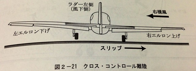
Generally speaking, after starting the takeoff roll, taking a left crosswind as an example, the pilot adopts the cross control (sideslip method), gently pressing the left rudder pedal, with the nose pointing slightly downwind (to the right) to counteract the weathercock effect of the left crosswind; At the same time, the left crosswind causes an imbalance in Lift generated by the two wings; the left wing has more Lift, and the right wing has less. To maintain balance, the pilot presses the control stick to the left to control and reduce the Lift of the left wing. Therefore, overall the Lift on both wings is equal, the aircraft is basically in a balanced and stable state, and the nose is basically facing the runway center.
The diagram below illustrates sideslip method control in a right crosswind situation; therefore, the control method and aircraft attitude are opposite to those described above.
But this is merely the operation in an ideal state; in reality, wind speed and direction are changing all the time. Pilots must adapt to the situation based on weather conditions and make flexible responses to various Wind shears instantly.
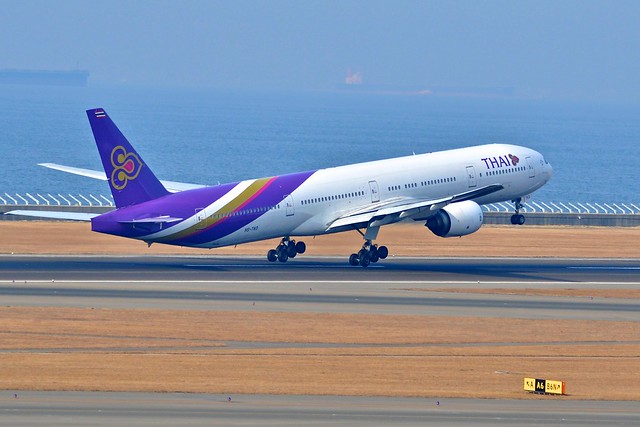
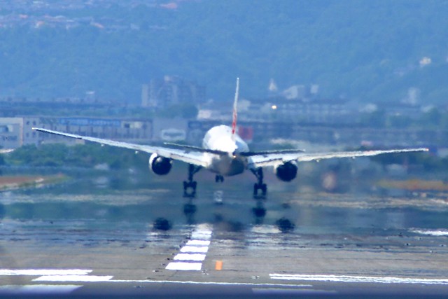
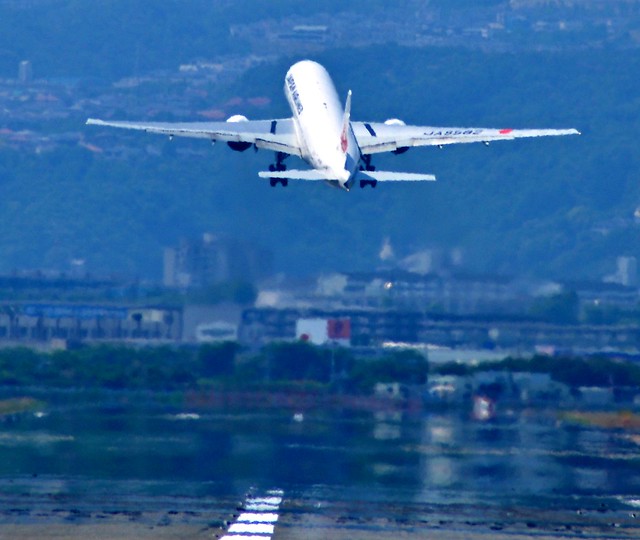
Recently, I went to Osaka International Airport and observed aircraft taking off and landing at the threshold of Runway 32L. I took a series of photos of a certain airline’s jet passenger plane, a Boeing 777, taking off in a left crosswind.
After the Vr speed, the pilot starts to pull back, and the nose raises. You can see the left wing is higher than the right wing,
and the left main landing gear also leaves the ground earlier than the right one.
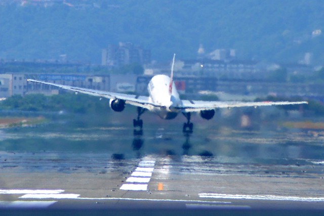
Perhaps the wind speed at this moment exceeded the pilot’s expectations, and the Lift on the left wing exceeded that on the right.
Therefore, the aircraft’s attitude was exactly the opposite of what was expected. The aircraft’s tilt (sideslip) and drift can be clearly seen.
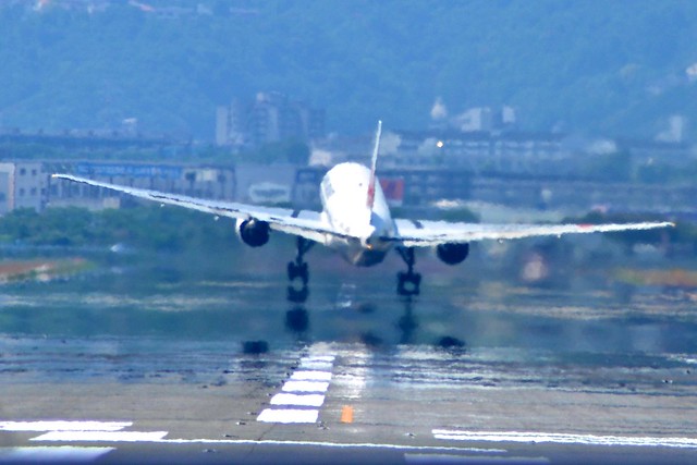
After the aircraft is completely airborne, the pilot transitions from sideslip correction to drift correction (crab method), that is, leveling the rudder and stick,
striving to keep both wings level, maintaining the Heading corrected for drift, and maintaining a normal Climb gradient.
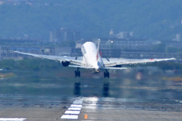

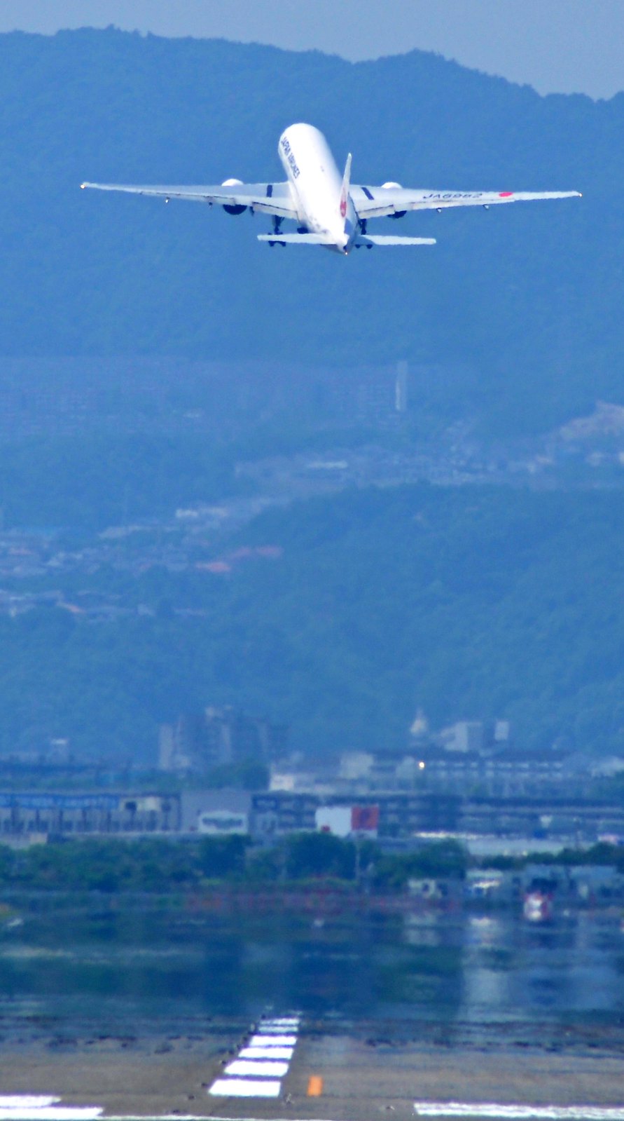
Throughout this series of operations, the aircraft’s forward direction was always maintained on the runway centerline, and even after Wind shear occurred, it basically did not deviate. The skills of professional pilots are truly high.
Prev: 起飞滑跑 TOC: 目录 Next: 收轮GEAR UP
End