Title: Airliner Cockpit Secrets 3.2 Takeoff Roll
Based on the weather and traffic conditions for the day, once the takeoff method has been decided, we finally enter the formal takeoff roll phase.
The Captain moves their left hand from the steering tiller to the control yoke, while their right hand remains on the engine thrust levers.
(Note: Boeing aircraft use a control yoke, while Airbus uses a side-stick, located on the pilot’s outer side, as shown below.
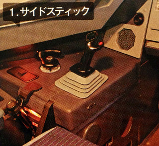
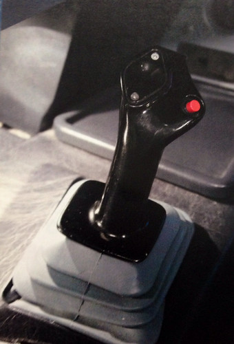 )
)
At this moment, if there is a crosswind, the control yoke should be tilted slightly towards the upwind direction. Because of the wind’s influence, the aircraft has a tendency to turn downwind during the takeoff run, so in order to maintain the heading, the pilot must pre-set the ailerons to adjust in the opposite direction. Pay attention to ensure the operation of the control yoke is gentle; it feels somewhat similar to the slight left and right adjustments made when driving a car straight on a highway.
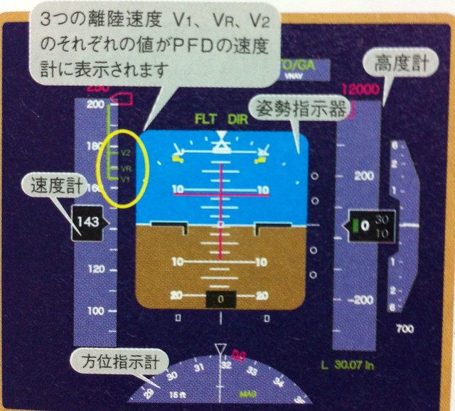
After the aircraft aligns with the Runway center line, the Captain checks the V1, Vr, and V2 speed displays on the PFD again.
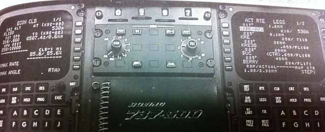
 On the ND map mode, the routes and Waypoints are displayed normally, and the CDU is set to the ECON CLIMB page.
The First Officer’s side CDU is set to the ROUTE LEGS page.
On the ND map mode, the routes and Waypoints are displayed normally, and the CDU is set to the ECON CLIMB page.
The First Officer’s side CDU is set to the ROUTE LEGS page.
Next, the Captain moves the A/T (Autothrottle) switch on the upper left of the MCP to the ARM position. This puts the thrust system into computer control mode.
From takeoff, Climb, cruise, Descent, all the way to landing, the process is basically automatically operated by the Flight Management Computer (FMC). The engine speed N1 limit is also controlled by the FMC. At the same time, the text “ARM” will appear in the mode bar at the top left of the PFD (Mark 2 in the image below).
 For the definition of each item in the mode bar, please refer to the image below.

After both pilots confirm and check the ARM mode, they check again on the ND that the Heading is set directly towards the Runway direction.
The Captain smoothly pushes the thrust levers forward with their right hand to the N1 40% position (taking a normal takeoff as an example, the 40% position is roughly equivalent to the adjacent Flaps 5 position).
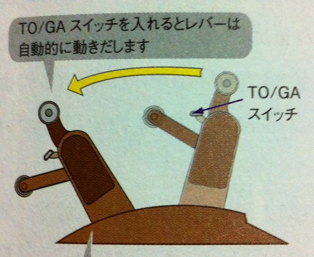
Observing the engine status and confirming that the thrust on both left and right engines is stable, the Captain uses their right index finger to press the black TO/GA button on the top of the thrust lever (Boeing aircraft) or pushes the throttle to the TO/GA position (Airbus).
TO/GA stands for Take Off/Go Around, which is the autothrust system for takeoff and go-around. Once the Boeing aircraft’s TO/GA button is pressed, the thrust levers automatically move forward and stay at the most appropriate throttle position calculated by the FMC (as shown below). Therefore, the pilot can understand the engine throttle setting by observing the instruments, or intuitively by looking directly at the position of the thrust levers.
The Airbus thrust device is designed quite differently from Boeing’s. When the throttle is set to the FLX or TOGA detent, the thrust levers stay in that position and do not change, but the throttle automatically increases with the computer’s control until the required thrust for takeoff is reached (as shown below).
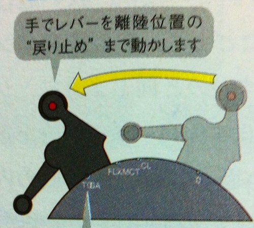 As you can see in the image above, the Airbus thrust consists of several fixed positions: “0 (Idle)”, “CL (Climb)”, “FLX (Flexible)/MCT (Maximum Continuous Thrust)”, and “TOGA (Takeoff Go Around)”.
Continuing with the Boeing 737 as an example, the mode display on the PFD will now show “N1, TO/GA, HDG SEL” (Mark 3 in the image below).
This means “Autothrottle, Takeoff Thrust, Heading Select” modes. The engine roar rises continuously, and the aircraft taxis forward continuously. Soon, the current speed is displayed in the box on the speed bar on the left side of the PFD.
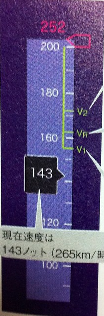
The First Officer monitors to ensure the engine oil pressure is within the yellow normal range. The Captain pushes the control yoke slightly forward to prevent the aircraft from pitching up early at insufficient speed due to the force acting on the horizontal stabilizer. At this point, the aircraft is about to reach V1 speed.
Prev: 3 Takeoff Methods TOC: Table of Contents Next: Takeoff Run
End