A Flight Sim Enthusiast's Notebook
-
Title: X-Plane Display Rendering Settings
X-Plane has powerful display capabilities. If you are pursuing various spectacular scenery and beautiful skies, the hardware requirements are quite high; you definitely need to buy a high-end graphics card with a large amount of video memory. However, since I mainly pursue the realism of flight, I have turned off many settings. Below are my personal settings for your reference (click to enlarge).
-thumb-660x500.png) You can see that basically none of the special effects settings are checked, and the number of objects on the ground is also set to very low. This is mainly to ensure smooth flight movements.
You can see that basically none of the special effects settings are checked, and the number of objects on the ground is also set to very low. This is mainly to ensure smooth flight movements. -
A Brief Discussion on Propeller Slipstream and P-Factor in Small Single-Engine Propeller Aircraft — Why Does My Plane Always Turn Left?
Most beginners to flight simulation encounter a common issue: after a small single-engine propeller plane accelerates on the ground, takes off, and leaves the ground, it fails to proceed in a straight line and instead veers constantly to the left. First of all, congratulations! The software you are using is authentically simulating the effects of aircraft aerodynamics. You have chosen excellent software!
Of course, X-Plane is precisely this kind of software that authentically simulates aerodynamics. You should know that its commercial version is certified by the Federal Aviation Administration (FAA) as an official simulator for pilot training. The flight control models in the home version we generally use and the commercial version of X-Plane are identical. Therefore, using X-Plane delivers an extremely realistic flying sensation, including propwash and P-Factor. In a foreign X-Plane forum I frequently follow, there was a discussion regarding realism, and some pilots with commercial licenses spoke highly of this software.
-
Title: Exploring the Cockpit of Airliners 4.2 What are the indicators of flight speed and what is the maximum speed of an aircraft?
During the cruise phase, even though the autopilot instruments on the aircraft are very advanced and pilots do not need to manipulate the controls directly, this does not mean pilots can be idle. They must constantly scan various instruments, check various flight data, and record it from time to time; they are still quite busy.
Below is a simple summary of flight data information across a few sections. First, let’s look at speed.
-
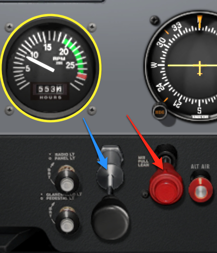
Title: A Brief Discussion on the Use of Mixture Control in Small Aircraft
As altitude increases, the air becomes thinner, reducing the amount of air entering the engine. If the amount of fuel delivered remains constant, the fuel mixture becomes too rich, which not only wastes fuel but also reduces engine output. This is where the Mixture Control valve comes in; it allows pilots to control the air-to-fuel ratio, giving you more precise control over the engine. This magical valve is the red handle indicated by the red arrow in the image below (Cessna 172SP in X-Plane 10).
-
Airliner Cockpit Secrets 4.1 Basics of Navigation
Once the aircraft enters the cruise phase, pilots can finally relax a bit and ease the tension built up since takeoff. Cabin attendants also bring coffee and other beverages to the cockpit; after all, the air inside the aircraft is dry, and pilots need to stay hydrated.
While they are resting, let’s take a brief pause to look back at the journey since takeoff.
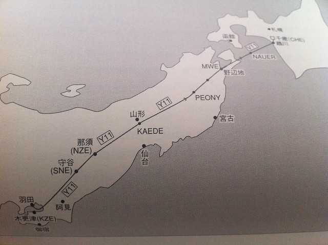
Taking flight JAS115 as an example, let’s first look at the route chart and the NAVIGATION LOG.
-
The Joy of Reading Charts
I previously read an English article introducing how to fly actual airline routes using X-Plane, and I found it very helpful. So, I downloaded and printed out real-world charts from the internet, carefully checked the flight route according to the instructions in the article, and drew it out on paper, which deepened my understanding of the airway significantly. The routes and chart materials introduced in the above text are as follows: 1 Cincinnati/Northern Kentucky International Jodub Two Standard Instrument Departure 2 High Altitude Enroute Chart US (HI) #4
-
Climb, Descent, and Level Flight Practice
I was away on another business trip for a week. In the spirit of not letting this blog go to waste, here is a quick update.
Yesterday after getting home, I fired up X-Plane for a bit of relaxation and focused on practicing the Vertical Speed during Climb and Descent.
For instance, maintaining the Vertical Speed at 1000 feet per minute, and noting the two points of applying gentle pull and push pressure when changing the pitch attitude.
-
Title: Into the Level Flight Cruise
At this point, the aircraft leaves the Tokyo North Kanto Area Control Center and begins to enter the Northeast Area. Taking the Boeing 777-200 “Air System 115” flight as an example, 16 minutes after takeoff, the aircraft has reached the Nasu area in Tochigi Prefecture, passing the NZE VOR navigation aid.
It has reached an altitude of 39,000 feet.
As seen in the image above, the aircraft entered the Y11 Airway of R-NAV (Area Navigation) starting from the Moriya SNE navigation aid, and will continue north along this airway all the way to the Chitose navigation aid in Hokkaido.
-
Plugin Introduction: Landing Speed Display and Evaluation X-Plane Landing Speed Plugin
Whether in real flight or flight simulation, the landing phase is basically considered the most difficult maneuver.
I discovered a nice Plugin/Addon that displays the vertical speed at touchdown and evaluates the landing operation, which is very helpful for practice. Here is an introduction.
First, regarding the installation method: download the old version from here or download the new version that supports 64-bit from here, and extract the files into the
Resources/pluginsdirectory under the main X-Plane directory. -
Airliner Cockpit Exploration 3.7 ATC Handoff to Center, Continue Climb
First, let’s take Air System Flight 115 from Tokyo Haneda Airport to Hokkaido Sapporo New Chitose Airport as an example again. Let’s look at the Air Traffic Control (ATC) process required for this flight from takeoff to cruise and landing:
1 Haneda Airport: Delivery Control — Ground Control — Tower Control — Departure Control 2 Area Control: Tokyo Control Area — Sapporo Control Area 3 New Chitose Airport: Approach Control — Tower Control — Ground Control
-
Title: Unveiling Airliner Cockpit Secrets 3.6 ATC Handover to Departure Control, Entering VNAV Mode
Taking AirSystem Flight 115 as an example, the aircraft follows the Moriya 7 Departure procedure at Haneda Airport. It first flies along the Runway (16R) direction to the KZE (KISARAZU) waypoint at the bottom right of the chart, then automatically banks left 30 degrees, turning to a 14-degree direction (basically close to due north) to fly towards the SNE (MORIYA) waypoint.
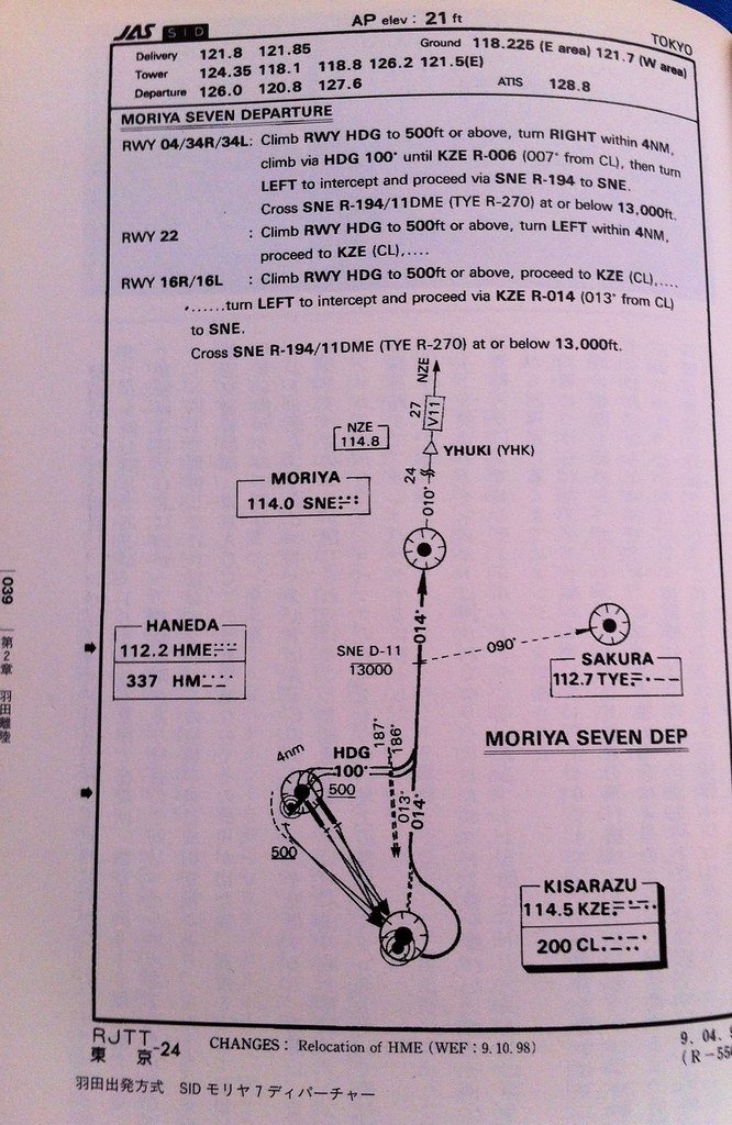
At this point, after the Tower controller confirms the aircraft’s departure is correct, they instruct the pilot to contact Departure Control: “Air System 115, Contact Departure” This means “Air System 115, contact Tokyo Departure” The First Officer replies “Departure, Air System 115” Meaning “Contacting Tokyo Departure, Air System 115” Then, tunes the radio frequency to Departure Control 120.800MHz, and calls: “Tokyo Departure, Air System 115, Leaving 1800” This means “Tokyo Departure, this is Air System 115, passing through 1800 feet” The controller replies “Air System 115, Tokyo Departure, Radar Contact, Turn Left Heading 020, Vector to Moriya, Climb and Maintain 210” This means “Air System 115, this is Tokyo Departure, radar contact, turn left heading 020, radar vector to Moriya, Climb and Maintain 21000 feet” The First Officer reads back: “Left 020, Direct 210, Air System 115” Meaning “Turn left heading 020, maintain 21000 feet, Air System 115”.
-
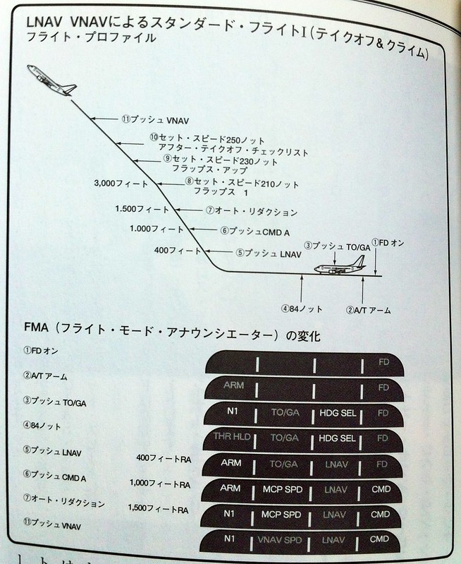
Title: Uncovering the Mysteries of Airliner Cockpits 3.5 Engage Autopilot
The aircraft continues to climb. The number on the radio altimeter exceeds 400 feet (using the 737-500 from the airliner pilot manual as an example). At this point, the LNAV (Lateral Navigation) mode can be engaged. The Captain instructs the First Officer to press the LNAV button on the MCP.
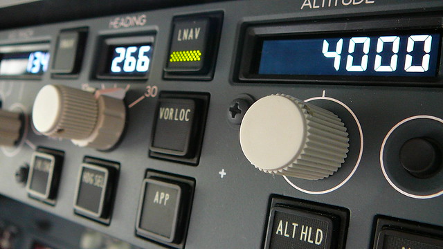
Consequently, in the mode annunciation at the top left of the PFD, the Heading setting changes from HDG SEL to LNAV, and the flight mode enters Phase 5 as shown in the figure below.
-
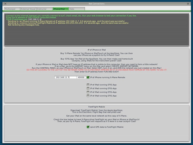
Title: New Features in X-Plane 10.10 Beta 9 -- Airport Map Navigation iPad App ForeFlight Mobile Support
X-Plane 10.10 Beta 9 is released, and it looks like a lot of bugs have been fixed. However, the highlight of this version is the support for the iPad/iPhone airport map navigation app, ForeFlight Mobile. It can display Visual Flight Charts, radar, flight plans, airport maps, and other information.
Here is a brief introduction on how to use it. First, upgrade X-Plane and install ForeFlight on your iPad/iPhone. After starting X-Plane, open the Internet option in the Settings menu, then select the iPhone/iPod tab and check the “ForeFlight Net Connections” item at the bottom of the screen, as shown below.
-
Free SkyVector Chart Website
Today, the flight chart website SkyVector has launched a worldwide charts service, and it’s free—truly a generous offering.
-thumb-640x507.png)
The service features a Google Maps-style interface with smooth zooming and panning operations. It provides high and low-resolution IFR and VFR charts, as well as weather information for various airports. It also includes a simple flight planning feature; after entering various Waypoints and speeds, it can automatically calculate flight distance and time. Although the functionality isn’t extremely powerful, it’s quite convenient as a reference.
-thumb-640x502.png)
-
Title: Secrets of Airliner Flying 3.4 Gear Up
Based on the Boeing 737-500 Operating Manual from the “Airline Pilot Handbook,” let’s continue discussing the operations after the aircraft lifts off the ground.
The previous section mentioned that the Captain should keep both feet off the rudder pedals and use only the control yoke or stick to control the aircraft’s pitch and roll attitudes.
You might ask: Isn’t the rudder necessary to control adverse yaw during rolls? Isn’t it important to “call the ball” by keeping the inclinometer centered in the Turn Coordinator?
-
Flying a Simulation Over the Diaoyu Islands
I’ve been traveling on business for weeks, and my blog has been neglected for a long time, which is very embarrassing.
During this period, another diplomatic crisis between China and Japan has emerged, and hostile sentiments between the peoples of the two countries have resurfaced. The Americans must be gloating on the sidelines, thinking their strategy of alienation is quite successful, right? I really hope this boring situation will end soon.
-
Title: Airliner Cockpit Secrets 3.3 Takeoff and Liftoff
As the aircraft’s speed continues to increase, a green arrow known as the speed trend vector will appear on the speed strip on the left side of the PFD.
 It indicates the current acceleration of the aircraft; the arrow pointing up shows the aircraft is accelerating, while down indicates deceleration.
The speed pointed to by the arrow is the predicted aircraft speed value 10 seconds in the future.
By observing the speed trend vector, the pilot can know the future speed trend of the aircraft, which is particularly helpful for control during the Takeoff and Departure phases.
It indicates the current acceleration of the aircraft; the arrow pointing up shows the aircraft is accelerating, while down indicates deceleration.
The speed pointed to by the arrow is the predicted aircraft speed value 10 seconds in the future.
By observing the speed trend vector, the pilot can know the future speed trend of the aircraft, which is particularly helpful for control during the Takeoff and Departure phases. -
Title: Airliner Cockpit Secrets 3.2 Takeoff Roll
Based on the weather and traffic conditions for the day, once the takeoff method has been decided, we finally enter the formal takeoff roll phase.
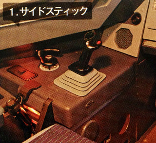
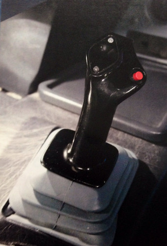
The Captain moves their left hand from the steering tiller to the control yoke, while their right hand remains on the engine thrust levers. (Note: Boeing aircraft use a control yoke, while Airbus uses a side-stick, located on the pilot’s outer side, as shown below.
 )
) -
Title: Unveiling Airliner Cockpit Secrets 3.1 3 Types of Takeoff Methods
Generally speaking, there are three takeoff methods for aircraft. Here is a brief introduction.
Normal Takeoff Method
The aircraft stops on the Runway with the nose facing the center line. While holding the brakes, push the thrust lever forward to N1 40%. After confirming stable engine operation, release the brakes and the aircraft begins to taxi. When the airspeed reaches 60 knots, set the Thrust to takeoff Thrust.
This method is primarily used in conditions such as crosswinds, wet Runways, or slippery Runways covered with ice or snow. Since it is crucial to maintain the stability of the nose Heading in these situations, this method of aligning with the Runway before applying full power is beneficial for maintaining direction. Additionally, the takeoff roll distance listed in aircraft performance specifications refers to data from this type of takeoff.
-
Title: Secrets of Airliner Flying 2.7 Takeoff Clearance
While the aircraft is taxiing, the First Officer tunes the communication frequency to the Tower band and contacts the Tower Controller: “Tokyo Tower, Air System 115, with you”
This means: “Tokyo Haneda Tower, this is Air System 115.”
The Tower Controller replies: “Air System 115, Tokyo Tower, Number 2”
Which means: “Air System 115, Tokyo Haneda Tower, you are number two for takeoff.”
Consequently, the First Officer reads back: “Number 2.”