X-Plane12 A330 POH 3
Primary Instrument Panels
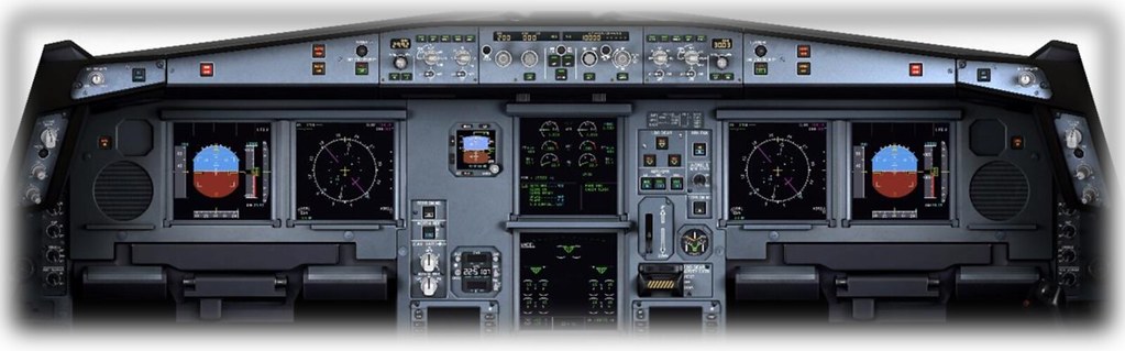
Primary Flight Display (PFD) This is the LCD panel on the left side of the avionics cluster. The PFD displays the aircraft’s attitude relative to the horizon, as well as altitude (relative to sea level), shown via the scale on the right. The attitude display informs the pilot whether the aircraft is flying straight or Turning, and whether the aircraft is Climbing or Descending. This information is critical during “instrument conditions,” i.e., when the external horizon is not visible. The PFD also displays altitude and Airspeed information, as well as localizer deviation and glideslope deviation when coupled with an ILS approach. Details of the PFD are introduced in a separate section: Primary Flight Display (PFD) Components.
Navigation Display (ND)
This is the LCD panel on the right side of the avionics cluster. The ND displays the aircraft’s position and (magnetic) Heading. This display presents a plan view, as if looking down at the aircraft from directly above. If a flight plan has been entered (using the FMS), this panel also shows the aircraft’s position relative to the desired Track. Details of the ND are introduced in a separate section: Navigation Display (ND) Components.
Integrated Standby Instrument System (ISIS) In the event of a primary PFD failure, this instrument provides redundancy. The ISIS is powered by an independent power source and uses dedicated gyroscopes and accelerometers. This instrument displays: Attitude; Airspeed; Altitude; Barometric pressure (user-settable); Airspeed scale (user-settable);
Electronic Centralized Aircraft Monitor (ECAM) / Engine and Warning Display This panel displays: Engine Pressure Ratio (EPR); Exhaust Gas Temperature (EGT); Low-pressure turbine speed (N1); High-pressure turbine speed (N2); Fuel quantity; Flaps and slats position; Details of this display panel are introduced in a separate section: ECAM Engine and Warning Display Components.
Electronic Centralized Aircraft Monitor (ECAM) / System Display Schematic diagrams of aircraft systems; Aircraft system status information; Details of this display panel are introduced in a separate section: ECAM System Display Components.
Landing Gear and Autobrake
The lever on the lower left of this panel is used to extend and retract the landing gear. There are three landing gear indicators at the top left of the panel, corresponding to the nose wheel and left/right main landing gear. When the landing gear is down and locked, the three indicators will illuminate green. When the landing gear is in motion, they will display amber unlocked status. When the landing gear is fully retracted, the indicators will show no status.
AUTO BRK: These buttons control the rate at which the autobrake applies during landing and rejected takeoffs. LO is used for landings on long/dry Runways. MED is used for landings on short/wet Runways. MAX is used for rejected takeoffs and can only be set on the ground. If spoilers are deployed during takeoff, the brakes will be triggered. TERR ON ND: Click this button to overlay terrain radar on the Navigation Display (ND) map.
Chronometer This instrument displays the current local time and accumulated flight time. It also features a timer for timing events in flight. CHR: Click this button to start and stop the timer. RST: Click this button to reset the timer. RUN: Click this button to start the (flight) accumulated timer. Only available during flight.
Primary Flight Display (PFD) Components

1 Autothrust Annunciator: Illuminates when the autopilot manages airspeed 2 Vertical Mode Annunciator: Illuminates when autopilot vertical mode is active 3 Lateral Mode Annunciator: Illuminates when autopilot lateral mode is active 4 Engagement Status: Displays engagement status of autopilot, flight director, and autothrottle 5 Selected Altitude: Altitude pre-selected by the crew 6 Managed Altitude: Altitude hold (actual stable altitude) (blue=selected/magenta=constraint) 7 Current Altitude 8 Altitude Trend Vector 9 Barometric Altitude Reference: Set by the crew 10 TRU (True) Annunciator: Illuminates if the Airspeed scale shows true airspeed (rather than indicated airspeed) 11 Static Reference Line: The static reference line shows the aircraft’s position relative to the artificial horizon, including Climb, Descent, Turn left, or Turn right 12 ILS Reciprocal: If the Heading scale exceeds the display range, it is shown here 13 Heading: Current Heading (magnetic) 14 Actual Track: Actual Track (Track over ground) 15 Selected Heading (Bug): Set by the crew 16 Selected Heading (Digital): Selected Heading displayed digitally - shown when the bug on the Heading scale is out of display range 17 Minimum Airspeed Limit Scale 18 Selected Airspeed: Set by the crew 19 Approach Target Speed: Desired approach speed 20 Airspeed Trend Vector 21 Airspeed: Current Airspeed (Indicated Airspeed, unless TRU annunciator is illuminated) 22 Maximum Airspeed Limit Scale 23 Roll Rate: Roll rate (10, 20, 30, 45, 67 degrees)
Navigation Display (ND) Components
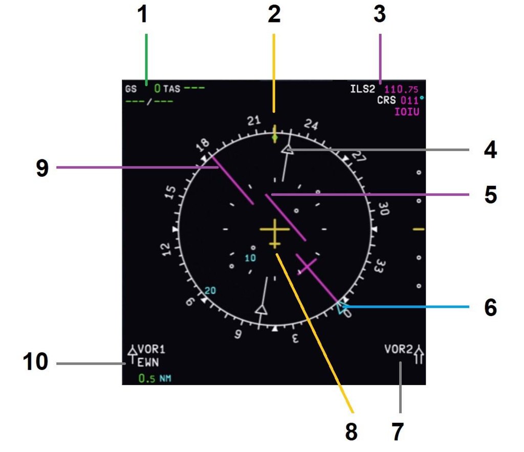 1 Speed: Ground speed/True airspeed
2 Current Heading
3 Waypoint/Navaid Info: Current Waypoint or Navaid information
4 VOR Heading: VOR Heading selected in VOR mode (Inbound/Outbound indicator)
5 CDI: Course deviation indicator from the Heading selected by the crew
6 Heading Bug: Heading selected by the crew for autopilot
7 VOR 2 Navaid Info: (If tuned) Navaid information for VOR 2 (selected by crew)
8 The Aircraft: Current plan view position and situation of the aircraft.
9 Selected Track: Track selected by the crew (Magenta for ILS, Blue for VOR)
10 VOR 1 Navaid Info: (If tuned) Navaid information for VOR 1 (selected by crew)
1 Speed: Ground speed/True airspeed
2 Current Heading
3 Waypoint/Navaid Info: Current Waypoint or Navaid information
4 VOR Heading: VOR Heading selected in VOR mode (Inbound/Outbound indicator)
5 CDI: Course deviation indicator from the Heading selected by the crew
6 Heading Bug: Heading selected by the crew for autopilot
7 VOR 2 Navaid Info: (If tuned) Navaid information for VOR 2 (selected by crew)
8 The Aircraft: Current plan view position and situation of the aircraft.
9 Selected Track: Track selected by the crew (Magenta for ILS, Blue for VOR)
10 VOR 1 Navaid Info: (If tuned) Navaid information for VOR 1 (selected by crew)
ECAM System Display Components (Upper)

1 EPR Engine Pressure Ratio: A measure of Thrust produced by the left and right engines. 2 EGT Exhaust Gas Temperature: Temperature of turbine exhaust gases expelled by the left and right engines (in Celsius). 3 Fuel Flow: Fuel flow of left and right engines (kg per hour) 4 Annunciator Message 5 Annunciator Message 6 N3 Rotational speed of the high-pressure turbines of the left and right engines (percentage of maximum)
ECAM System Display Components (Lower)
The lower ECAM displays schematic diagrams of aircraft systems, controlled by buttons on the ECAM control panel.
 ECAM Control Panel
ECAM Upper Display Knob: Controls the brightness of the upper ECAM display.
ECAM Lower Display Knob: Controls the brightness of the lower ECAM display.
Buttons: Refer to the table below
ECAM Control Panel
ECAM Upper Display Knob: Controls the brightness of the upper ECAM display.
ECAM Lower Display Knob: Controls the brightness of the lower ECAM display.
Buttons: Refer to the table below
ECAM Control Panel Modes
ENG Engine
 Engine Mode:
• All major engine parameters;
• F.USED: Fuel used;
• OIL: Oil quantity for left and right engines (quarts);
• PSI: Engine oil pressure and temperature;
• VIB N1, N2, N3: Turbine vibration (in Hertz [0.5 to 1,000]);
• NAC: Inlet inlet temperature (left and right engines, Celsius);
Engine Mode:
• All major engine parameters;
• F.USED: Fuel used;
• OIL: Oil quantity for left and right engines (quarts);
• PSI: Engine oil pressure and temperature;
• VIB N1, N2, N3: Turbine vibration (in Hertz [0.5 to 1,000]);
• NAC: Inlet inlet temperature (left and right engines, Celsius);
BLEED
 Bleed Mode:
• Pack outlet temperature;
• Compressed air pressure;
• Compressed air valve position;
• Outside air temperature;
• Gross weight;
Bleed Mode:
• Pack outlet temperature;
• Compressed air pressure;
• Compressed air valve position;
• Outside air temperature;
• Gross weight;
PRESS
 Pressure Mode:
• Landing altitude;
• Cabin differential pressure;
• Cabin vertical speed;
• Cabin altitude;
• Cabin inlet and exhaust valve positions;
• Safety valve position;
• Outside air temperature;
• Gross weight;
Pressure Mode:
• Landing altitude;
• Cabin differential pressure;
• Cabin vertical speed;
• Cabin altitude;
• Cabin inlet and exhaust valve positions;
• Safety valve position;
• Outside air temperature;
• Gross weight;
EL/AC
 Electrical AC Mode:
• Generator status;
• Generator load;
• Generator voltage;
• Generator AC (output) frequency;
• Outside air temperature;
• Gross weight;
Electrical AC Mode:
• Generator status;
• Generator load;
• Generator voltage;
• Generator AC (output) frequency;
• Outside air temperature;
• Gross weight;
EL/DC
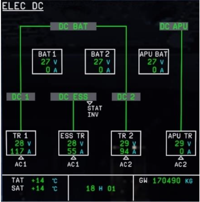 Electrical DC Mode:
• Battery status;
• Battery voltage;
• Transformer status;
• Transformer voltage;
• Outside air temperature;
• Gross weight;
Electrical DC Mode:
• Battery status;
• Battery voltage;
• Transformer status;
• Transformer voltage;
• Outside air temperature;
• Gross weight;
HYD
 Hydraulic Mode:
• Hydraulic system pressure;
• Status of electrical systems powering the Green/Blue/Yellow hydraulic systems;
• Status of the Ram Air Turbine powering the Green hydraulic system (extended or stowed);
• Outside air temperature;
• Gross weight;
Hydraulic Mode:
• Hydraulic system pressure;
• Status of electrical systems powering the Green/Blue/Yellow hydraulic systems;
• Status of the Ram Air Turbine powering the Green hydraulic system (extended or stowed);
• Outside air temperature;
• Gross weight;
APU
 APU Mode:
• APU bleed valve position;
• APU RPM;
• APU exhaust temperature;
• Outside air temperature;
• Gross weight;
APU Mode:
• APU bleed valve position;
• APU RPM;
• APU exhaust temperature;
• Outside air temperature;
• Gross weight;
COND
 COND Mode:
• Cockpit and cabin zone temperatures;
• Hot and cold air valve positions;
• Outside air temperature;
• Gross weight;
COND Mode:
• Cockpit and cabin zone temperatures;
• Hot and cold air valve positions;
• Outside air temperature;
• Gross weight;
DOOR
 DOOR Mode:
• Door position;
• Emergency slide status;
• Outside air temperature;
• Gross weight;
DOOR Mode:
• Door position;
• Emergency slide status;
• Outside air temperature;
• Gross weight;
WHEEL
 Wheel Mode:
• Landing gear status;
• Landing gear door position;
• Outside air temperature;
• Gross weight;
Wheel Mode:
• Landing gear status;
• Landing gear door position;
• Outside air temperature;
• Gross weight;
F/CTL
 Flight Control Mode:
• Aileron position;
• Primary and secondary flight control computer status;
• Pitch trim position;
• Elevator position;
• Rudder position;
• Rudder trim position;
• Outside air temperature;
• Gross weight;
Flight Control Mode:
• Aileron position;
• Primary and secondary flight control computer status;
• Pitch trim position;
• Elevator position;
• Rudder position;
• Rudder trim position;
• Outside air temperature;
• Gross weight;
FUEL
 Fuel Mode:
• Fuel usage indication;
• Fuel flow valve position;
• Fuel tank capacity;
• Total fuel flow;
• Total fuel quantity;
• Outside air temperature;
• Gross weight;
Fuel Mode:
• Fuel usage indication;
• Fuel flow valve position;
• Fuel tank capacity;
• Total fuel flow;
• Total fuel quantity;
• Outside air temperature;
• Gross weight;
ALL
 All Mode:
• Left and right engine high-pressure turbine (N2) speed;
• Total fuel used for left and right engines;
• Oil quantity for left and right engines;
• Left and right engine oil pressure and temperature;
• N1, N2, N3 turbine vibration (in Hertz [0.5 to 1,000]);
• Left and right engine inlet inlet temperature;
• Outside air temperature;
• Gross weight;
All Mode:
• Left and right engine high-pressure turbine (N2) speed;
• Total fuel used for left and right engines;
• Oil quantity for left and right engines;
• Left and right engine oil pressure and temperature;
• N1, N2, N3 turbine vibration (in Hertz [0.5 to 1,000]);
• Left and right engine inlet inlet temperature;
• Outside air temperature;
• Gross weight;