X-Plane 11 G530 Navigator Usage Tutorial
The G530 navigation equipment built into X-Plane 11 is very convenient. Here is a brief introduction to how to use it.
Using the default C172, you can see the striking 3D G530 in the 3D cockpit.
 0 Display and Button Explanation
1 Frequency Tuning
2 Navigation NAV Mode
3 Waypoint Mode
4 Nearest Mode
5 Flight Plan Mode
6 Creating a Flight Plan
7 Direct To Waypoint
8 Activate Jump / Activate Waypoint
9 Activate Approach
10 Loading Flight Plan Files
11 OBS Function
12 Suspend Mode
13 System Messages
14 Autopilot
0 Display and Button Explanation
Clicking with the mouse pops up a magnified 2D window, which is easier to operate.
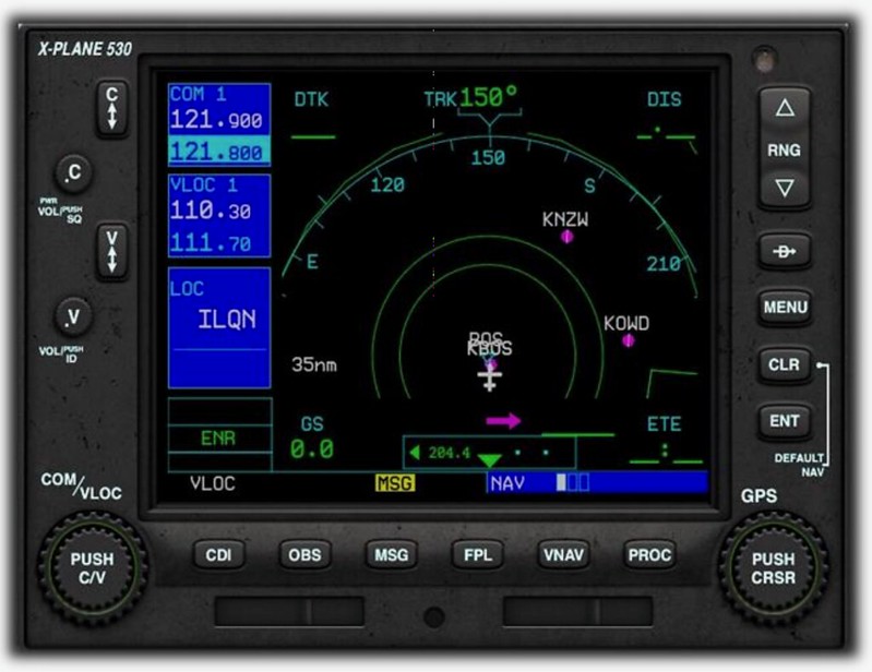 The central display area of the G530 is divided into two parts:
The left 1/4 is the frequency selection area (COM window, VLOC window, flight phase status display),
The right 3/4 is the navigation area (GPS window, featuring NAV mode, Waypoints mode, etc.).
The bottom of the screen is the status bar; the blue bar on the right shows the mode of the navigation area.
In the image above, it indicates the current mode is NAV mode. The three small boxes indicate that this mode has 3 pages.
The white box indicates that it is currently on page 1.
The central display area of the G530 is divided into two parts:
The left 1/4 is the frequency selection area (COM window, VLOC window, flight phase status display),
The right 3/4 is the navigation area (GPS window, featuring NAV mode, Waypoints mode, etc.).
The bottom of the screen is the status bar; the blue bar on the right shows the mode of the navigation area.
In the image above, it indicates the current mode is NAV mode. The three small boxes indicate that this mode has 3 pages.
The white box indicates that it is currently on page 1.
The description of the buttons on the left and right sides is as follows:
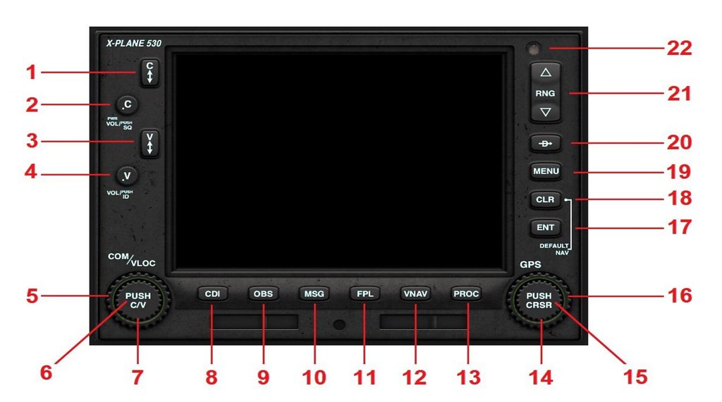 1 Comm Frequency Flip-Flop Key: Used to swap current/standby Comm frequencies
2 Comm Volume & Squelch: Volume, but ineffective in XP
3 VLOC (VOR / Localizer) Frequency Flip-Flop Key: Used to swap current/standby nav radio frequencies
4 VLOC (VOR / Localizer) ID Volume & Squelch: Volume for Morse code identifiers of nav aids
5 Comm / VLOC Outer Rotary Control: Large standby frequency (before decimal point) adjustment knob
6 Comm / VLOC Inner Rotary Control Center (Push Button): Button to toggle between activating Comm and ground nav radio
7 Comm / VLOC Inner Rotary Control: Small standby frequency (after decimal point) adjustment knob
8 Course Deviation Indicator (CDI) button: CDI button, switches between VLOC (ground nav radio) and GPS (satellite navigation) modes
9 Omni Bearing Selector (OBS) button: OBS button, displays the VOR radial on screen
10 Message (MSG) button: Displays system messages and alerts
11 Flight Plan (FPL) button: Flight plan functions
12 Vertical Navigation (VNAV) button: Vertical navigation
13 Procedures (PROC) button: Arrival and departure procedures
14 GPS Inner Rotary Control: Multi-function small adjustment knob, function varies by current display mode
15 GPS Inner Rotary Control Center (Cursor Button): Multi-function button, function varies by current display mode
16 GPS Outer Rotary Control: Multi-function large adjustment knob, function varies by current display mode
17 Enter (ENT) button: Enter, confirm, move to next item
18 Clear (CLR) button: Clear, cancel
19 MENU button: Menu key
20 Direct To button: Direct-to key
21 Range (RNG) button (up or down): Adjusts map range scale
1 Comm Frequency Flip-Flop Key: Used to swap current/standby Comm frequencies
2 Comm Volume & Squelch: Volume, but ineffective in XP
3 VLOC (VOR / Localizer) Frequency Flip-Flop Key: Used to swap current/standby nav radio frequencies
4 VLOC (VOR / Localizer) ID Volume & Squelch: Volume for Morse code identifiers of nav aids
5 Comm / VLOC Outer Rotary Control: Large standby frequency (before decimal point) adjustment knob
6 Comm / VLOC Inner Rotary Control Center (Push Button): Button to toggle between activating Comm and ground nav radio
7 Comm / VLOC Inner Rotary Control: Small standby frequency (after decimal point) adjustment knob
8 Course Deviation Indicator (CDI) button: CDI button, switches between VLOC (ground nav radio) and GPS (satellite navigation) modes
9 Omni Bearing Selector (OBS) button: OBS button, displays the VOR radial on screen
10 Message (MSG) button: Displays system messages and alerts
11 Flight Plan (FPL) button: Flight plan functions
12 Vertical Navigation (VNAV) button: Vertical navigation
13 Procedures (PROC) button: Arrival and departure procedures
14 GPS Inner Rotary Control: Multi-function small adjustment knob, function varies by current display mode
15 GPS Inner Rotary Control Center (Cursor Button): Multi-function button, function varies by current display mode
16 GPS Outer Rotary Control: Multi-function large adjustment knob, function varies by current display mode
17 Enter (ENT) button: Enter, confirm, move to next item
18 Clear (CLR) button: Clear, cancel
19 MENU button: Menu key
20 Direct To button: Direct-to key
21 Range (RNG) button (up or down): Adjusts map range scale
1 Frequency Tuning Adjusting frequencies on the left side is relatively simple. Press button 6 to select whether to set Comm (COM1) or ground nav radio (NAV1), Then use buttons 5 and 7 to select the standby frequency, and finally use button 1 or 3 to activate it.
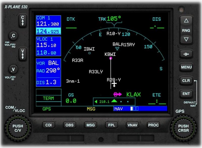
2 Navigation NAV Mode
Long press the CLR button (18) to enter NAV mode.
Page 1: Default map page, aircraft position fixed at bottom center. The Track in the map is 105 degrees.
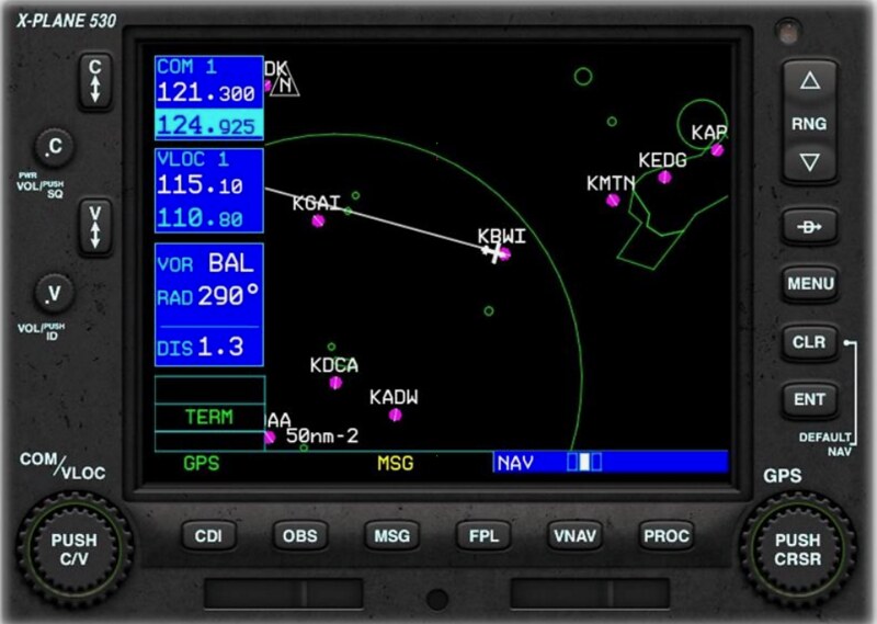
 Page 2: North-up map page, aircraft position fixed in the center of the screen. The Track in the map is 105 degrees, so the direction of flight is to the lower right.
 Page 3: VNAV page, allows for vertical navigation settings.
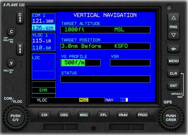 Use the small adjustment knob (14) to switch between pages.
The VNAV page above shows a Descent to KSFO San Francisco Airport set up. The pilot plans to Descend at 500 feet per minute to a 5-mile final altitude of 1000 feet. To set this, press the multi-function button (15) to enter edit mode. Use the large adjustment knob (16) to move between fields. Use the small adjustment knob (14) to adjust each field value. Press the multi-function button (15) again to exit edit mode.
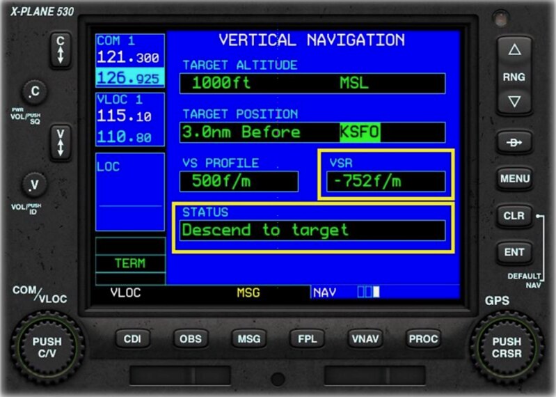 During flight, this page displays VSR (Vertical Speed Required) and status values.
In the image, the pilot needs to Descend at a rate of 752 feet per minute to reach the Destination 3 miles from the airport.
During flight, this page displays VSR (Vertical Speed Required) and status values.
In the image, the pilot needs to Descend at a rate of 752 feet per minute to reach the Destination 3 miles from the airport.
3 Waypoint Mode
Long press the CLR button (18) to enter NAV mode, then use the large adjustment knob (16) to switch to Waypoint mode.
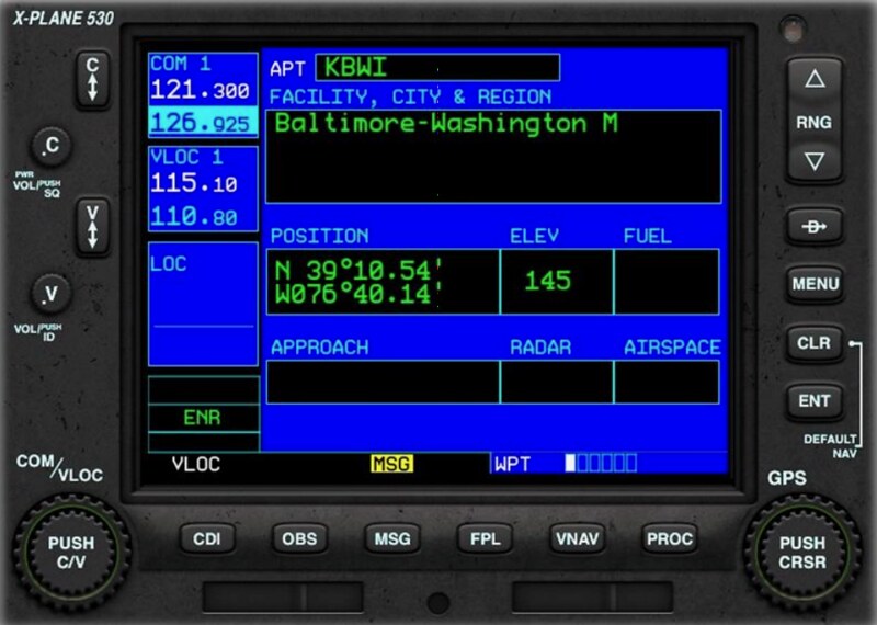
The status bar at the bottom right will display “WPT”.
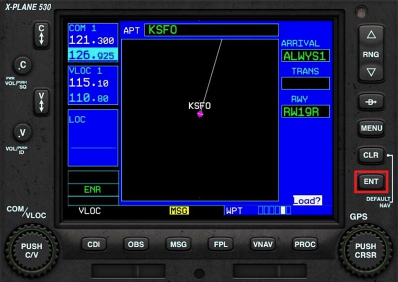
Page 1: Basic airport location
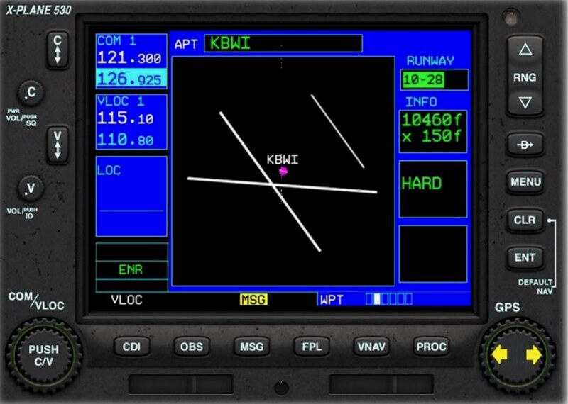
 Page 2: Airport Runway information
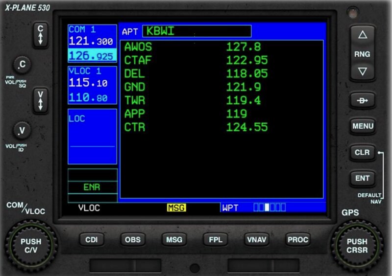
 Page 3: Airport frequencies
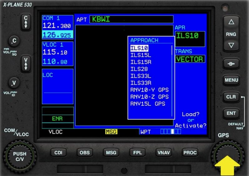
 Page 4: Airport approach procedures
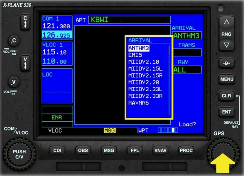
 Page 5: Airport arrival procedures
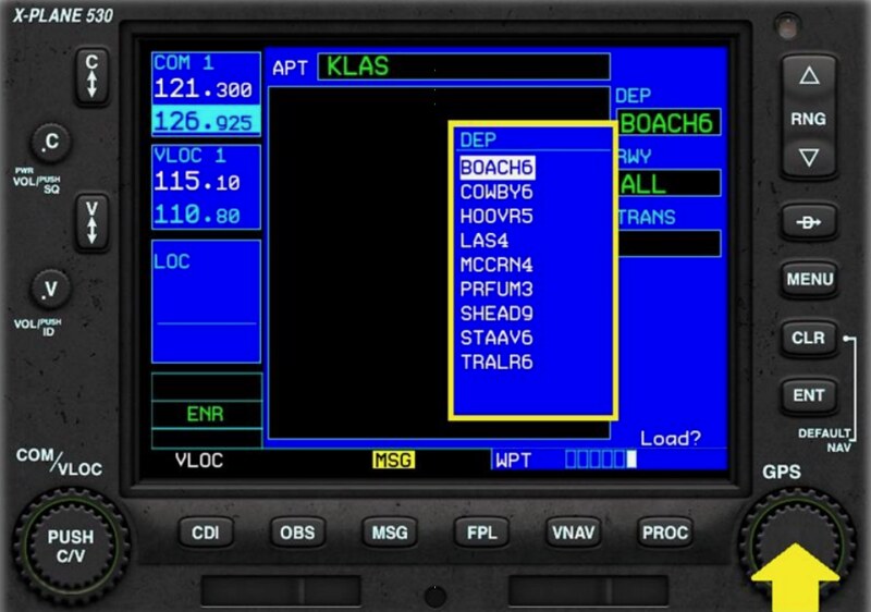
 Page 6: Airport departure procedures
The specific setting method is basically the same as above. Press the multi-function button (15) to enter edit mode. Use the large adjustment knob (16) to move between fields. Use the small adjustment knob (14) to adjust each field value. After changing the procedure, the screen will display “Load? or Activate?”. Press the ENT button to Activate, or the CLR button to Cancel or Delete.
4 Nearest Mode Long press the CLR button (18) to enter NAV mode, then use the large adjustment knob (16) to switch to Nearest mode. The status bar at the bottom right will display “NRST”.
Page 1: List of nearest airports, Bearing, Distance, and Approach type are also displayed.
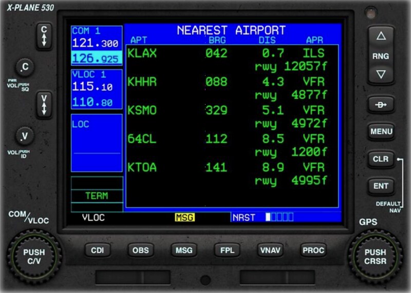 The specific setting method is basically the same as above.
Press the multi-function button (15) to enter edit mode.
Use the large adjustment knob (16) to move the cursor between airport items.
After selecting the airport, press the “Direct To” button (20),
Then press the ENT button.
The specific setting method is basically the same as above.
Press the multi-function button (15) to enter edit mode.
Use the large adjustment knob (16) to move the cursor between airport items.
After selecting the airport, press the “Direct To” button (20),
Then press the ENT button.
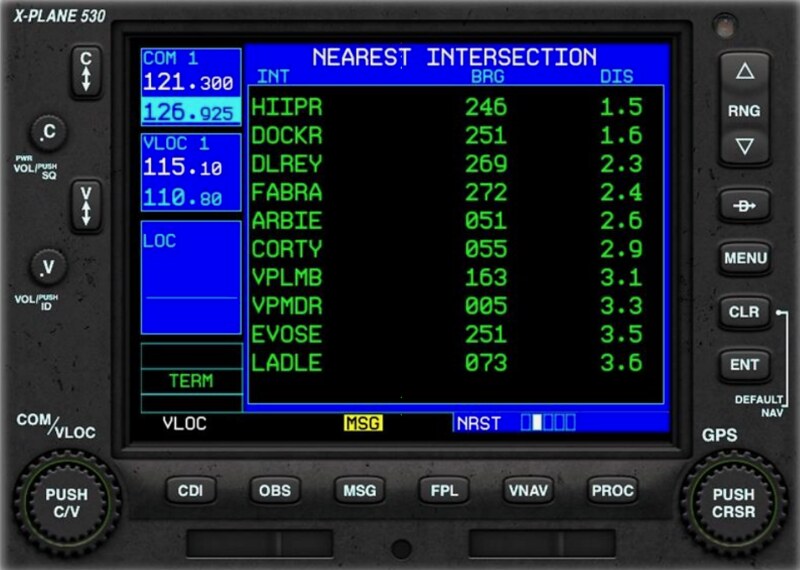
Page 2: Nearest intersection Waypoints, Bearing, and Distance are also displayed.
 Page 3: Names of nearest NDB navigation aids, Bearing, Distance, and Frequency are also displayed.
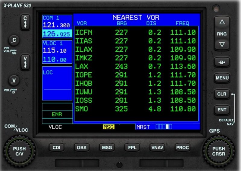
 Page 4: Names of nearest VOR navigation aids, Bearing, Distance, and Frequency are also displayed.
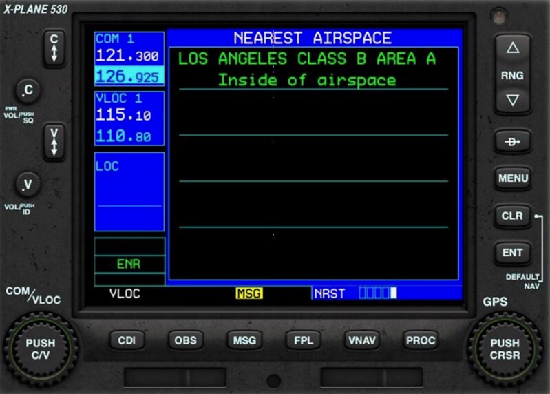
 Page 5: Names of nearest Airspace sectors.
 The methods for setting Direct To to Waypoints, NDBs, and VORs are the same as for Direct To Airport, so I won’t repeat them here.
5 Flight Plan Mode In NAV mode, press the Flight Plan (FPL) button (11) to enter Flight Plan mode. The status bar at the bottom right will display “FPL”.
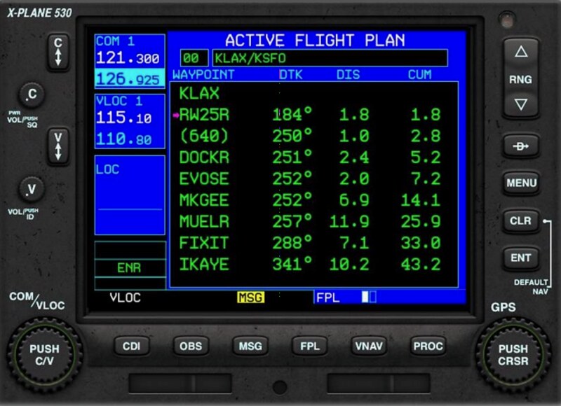
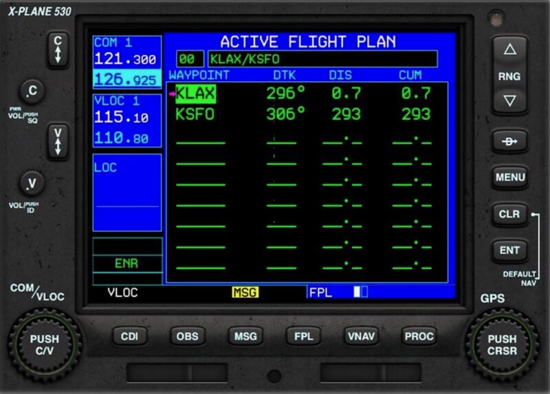
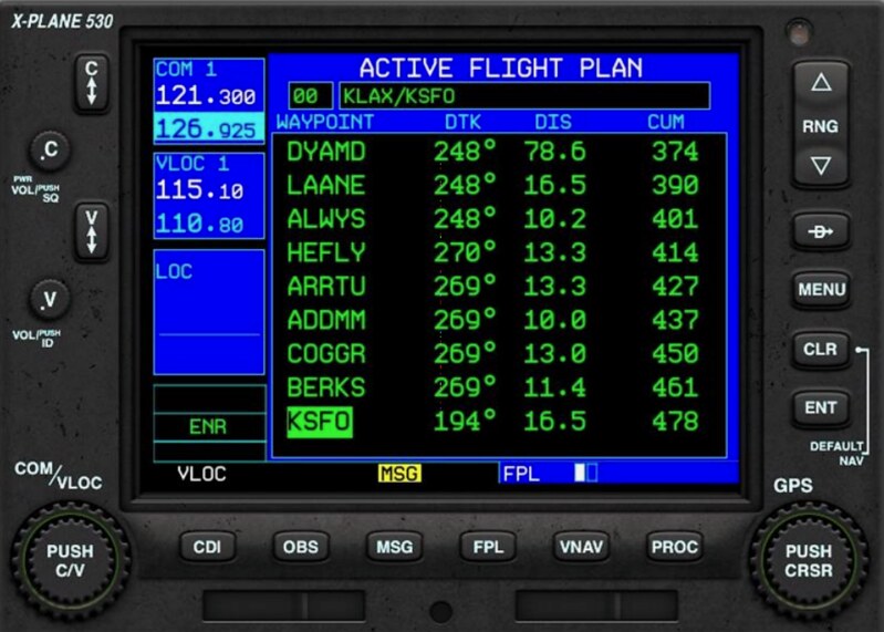
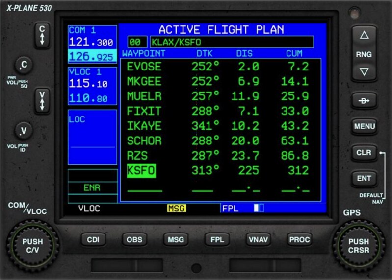
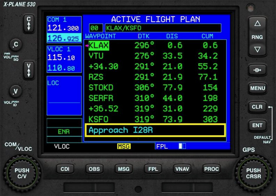
Page 1: Flight plan for current flight status, Waypoints, Bearing, leg distance, and total distance are displayed.
 Page 2: List of saved flight plans in the G530.
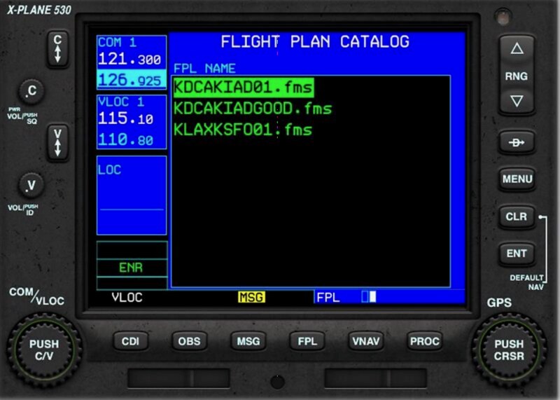 FMS files are saved in the computer’s /X-Plane 11/Output/FMS Plans directory.
6 Creating a Flight Plan
6.1 Delete current flight plan
In FPL mode, on the current flight status page, press the MENU button to activate the function menu.
Use the small adjustment knob (14) to select the “Delete Flight Plan” menu item.
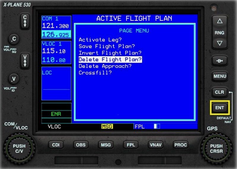 Press the ENT button to delete the current flight plan.
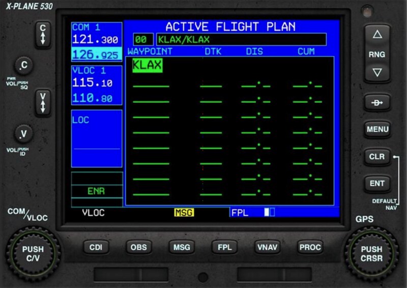
6.2 Create new flight plan
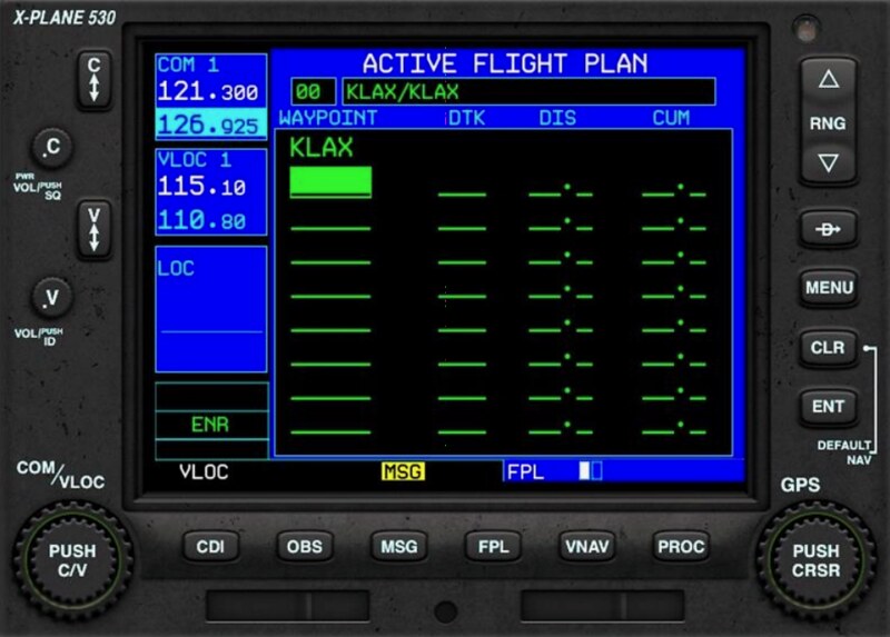
In FPL mode, on the current flight status page, you will see a new blank plan screen.
Press the multi-function button (15) to enter edit mode.
You will see the initial departure airport KLAX highlighted.
Use the large adjustment knob (16) to keep the cursor on the row where you want to add.
Use the small adjustment knob (14) to select the first character.
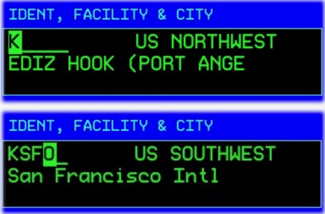 After selection, use the large adjustment knob (16) to move the cursor to the next character.
Continue using the small adjustment knob (14) to select characters until all Waypoints are entered.
After selection, use the large adjustment knob (16) to move the cursor to the next character.
Continue using the small adjustment knob (14) to select characters until all Waypoints are entered.
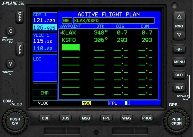 Press the ENT button twice to save the current flight plan.
6.3 Delete a Waypoint
In FPL mode, on the current flight status page:
Press the multi-function button (15) to enter edit mode.
Use the large adjustment knob (16) to move the cursor to the row you wish to delete.
Press the Clear (CLR) button (18), and a deletion prompt will pop up.
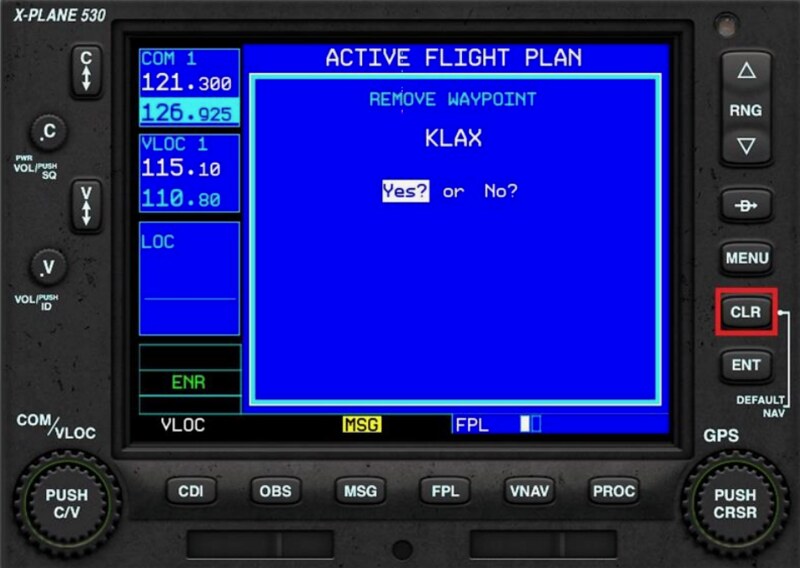 Use the small adjustment knob (14) to select Yes or No.
Press the ENT button to save the current flight plan.
Use the small adjustment knob (14) to select Yes or No.
Press the ENT button to save the current flight plan.
6.4 Set Standard Instrument Departure (SID)
In FPL mode, on the current flight status page:
Press the multi-function button (15) to enter edit mode.
Use the large adjustment knob (16) to move the cursor to the row for the departure airport KLAX.
Press the Procedures (PROC) button (13). The system will pop up the procedures menu.
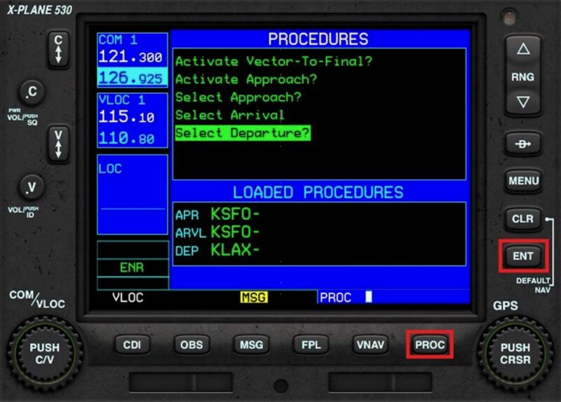 Use the small adjustment knob (14) to select the “Select Departure” menu item and press the ENT button.
The system will pop up a list of departure procedures.
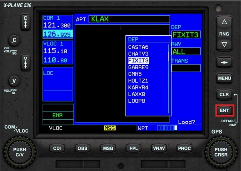 Use the small adjustment knob (14) to select the desired SID (Standard Instrument Departure) and press the ENT button.
The system will pop up a list of usable Runways.
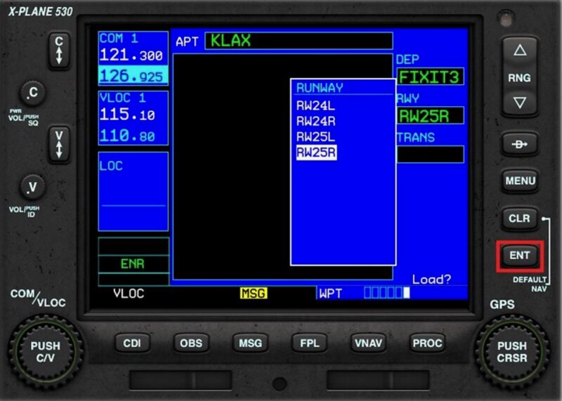 Use the small adjustment knob (14) to select the desired Runway and press the ENT button.
The system will pop up a list of transition Waypoints.
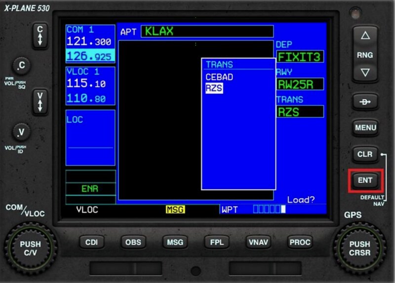 Use the small adjustment knob (14) to select the desired Waypoint and press the ENT button.
The system displays the departure route map.
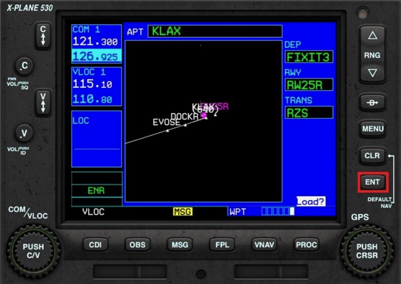 Press the ENT button to activate the flight plan.
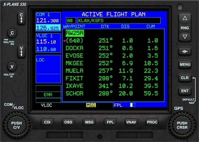
In FPL mode, on the current flight status page, the newly added Waypoints are displayed.
6.5 Set Standard Instrument Arrival (STAR)
In FPL mode, on the current flight status page:
Press the multi-function button (15) to enter edit mode.
Use the large adjustment knob (16) to move the cursor to the row for the destination airport KSFO.
Press the Procedures (PROC) button (13). The system will pop up the procedures menu.
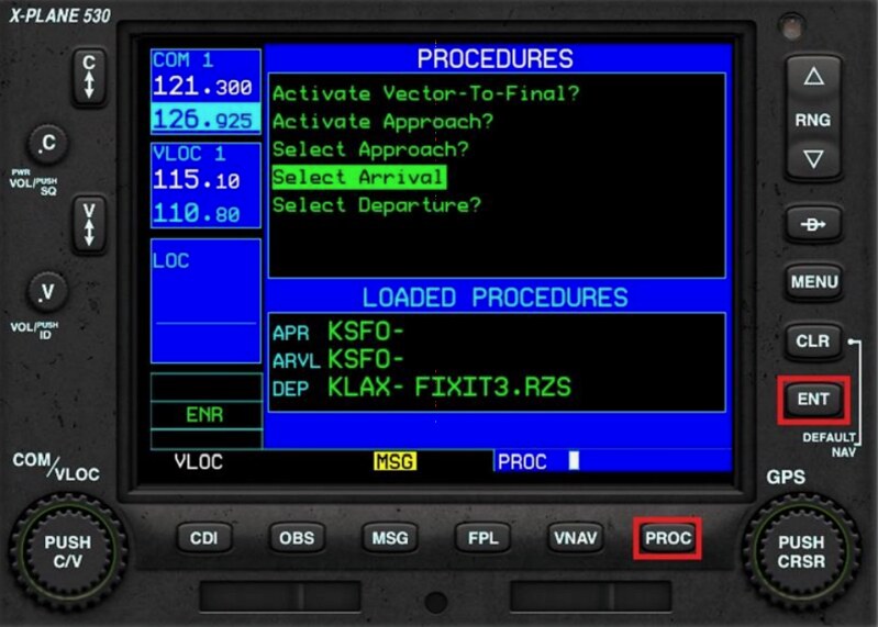 Use the small adjustment knob (14) to select the “Select Arrival” menu item and press the ENT button.
The system will pop up a list of arrival procedures.
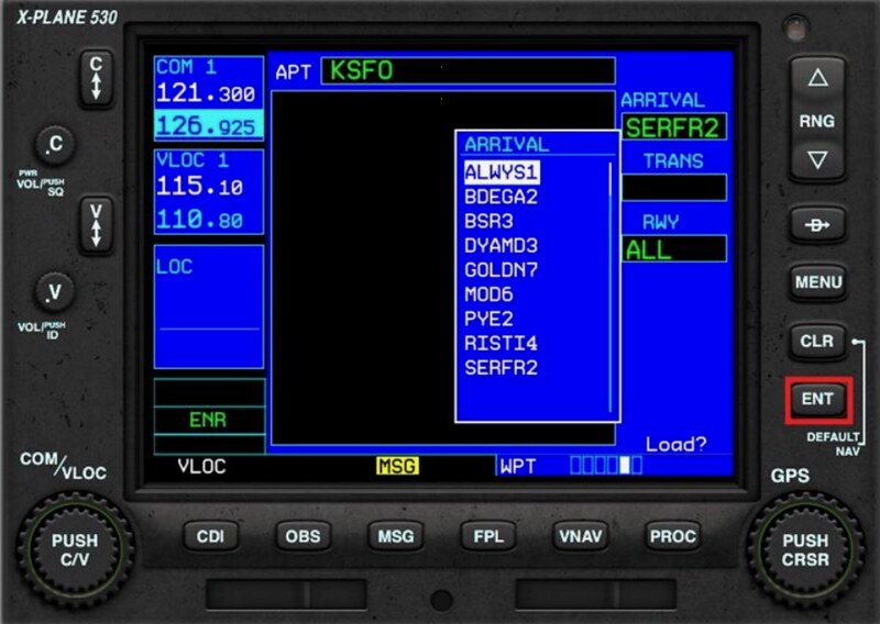 Use the small adjustment knob (14) to select the desired Standard Instrument Arrival and press the ENT button.
The system will pop up a list of transition Waypoints.
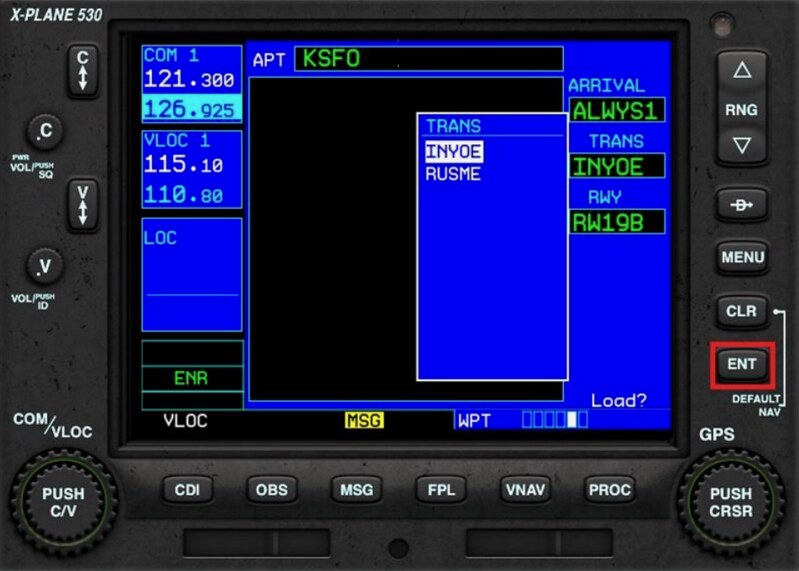 Use the small adjustment knob (14) to select the desired Waypoint and press the ENT button.
The system will pop up a list of usable Runways.
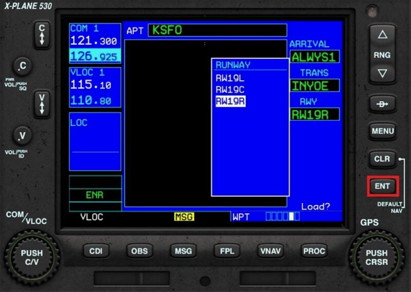 Use the small adjustment knob (14) to select the desired Runway and press the ENT button.
The system displays the arrival route map.
 Press the ENT button to activate the flight plan.
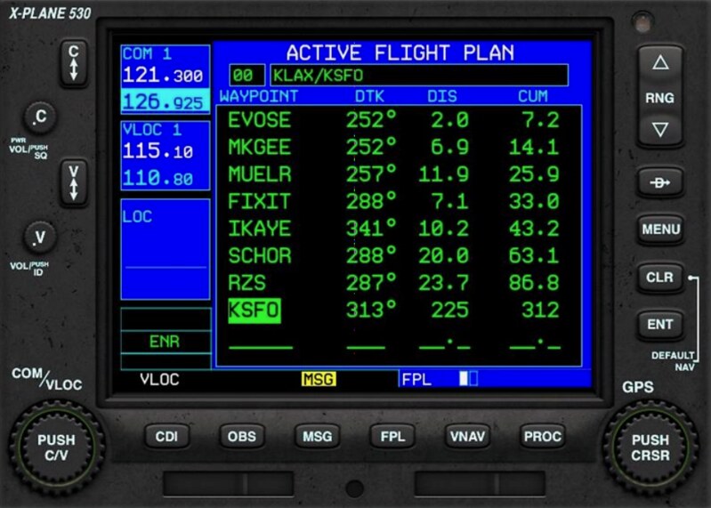
In FPL mode, on the current flight status page, the newly added Waypoints are displayed.
6.6 Set Approach
In FPL mode, on the current flight status page:
Press the multi-function button (15) to enter edit mode.
Use the large adjustment knob (16) to move the cursor to the row for the destination airport KSFO.
Press the Procedures (PROC) button (13). The system will pop up the procedures menu.
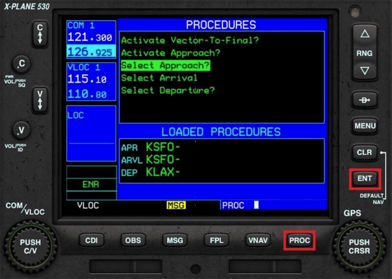 Use the small adjustment knob (14) to select the “Select Approach” menu item and press the ENT button.
The system will pop up a list of approach procedures.
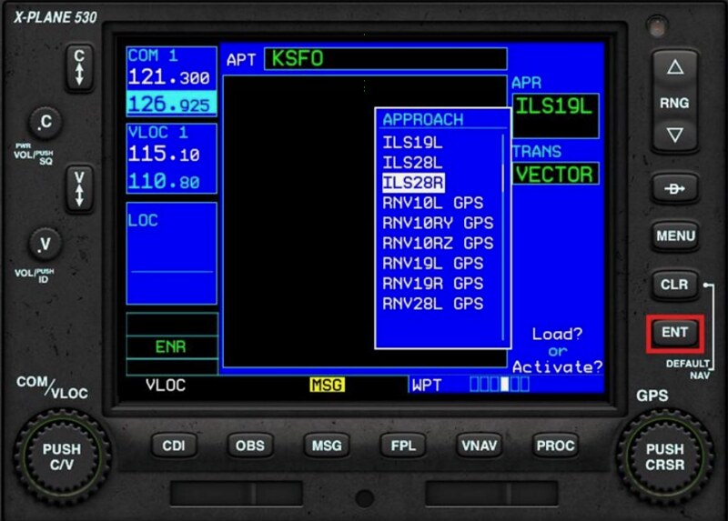 Use the small adjustment knob (14) to select the desired Approach and press the ENT button.
The system will pop up a list of Initial Approach Fixes (IAF).
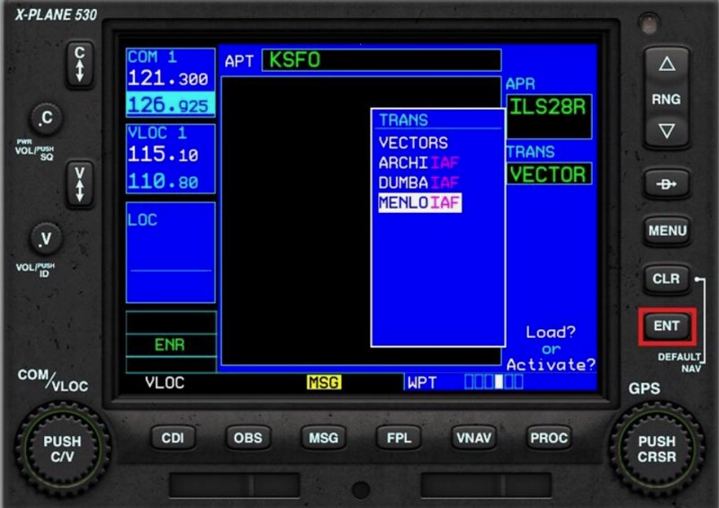 Use the small adjustment knob (14) to select the desired IAF and press the ENT button.
If ATC issues a non-standard Waypoint (vectors), use the “VECTORS” item here.
Use the small adjustment knob (14) to select the desired IAF and press the ENT button.
If ATC issues a non-standard Waypoint (vectors), use the “VECTORS” item here.
The system displays the approach route map.
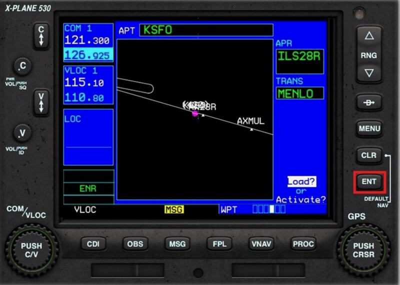 Press the ENT button to activate the flight plan.
In FPL mode, on the current flight status page, the newly added Waypoints are displayed.
7 Direct To Waypoint
In FPL mode on the current flight status page, or on the Nearest page:
Press the multi-function button (15) to enter edit mode.
Use the large adjustment knob (16) to move the cursor to the row of the target Waypoint.
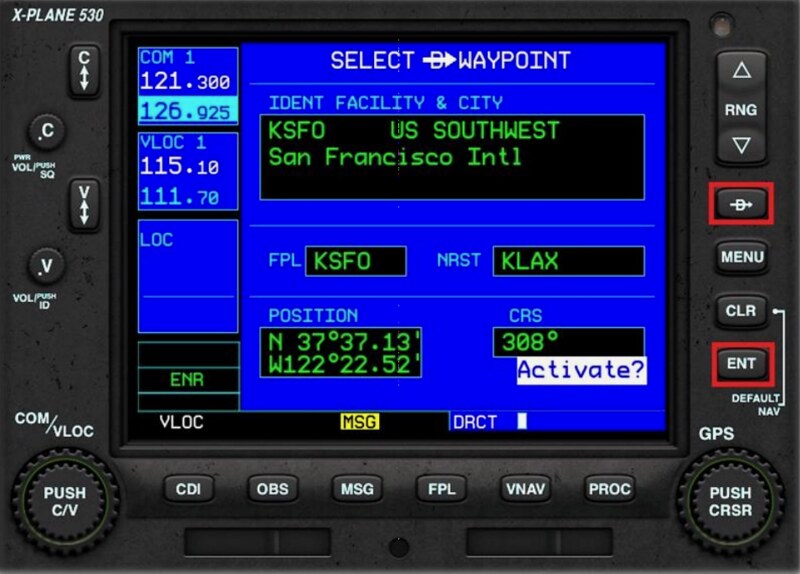 Press the Direct To button (20) and press the ENT button.
8 Direct Jump / Activate Waypoint
In FPL mode on the current flight status page:
Press the multi-function button (15) to enter edit mode.
Use the large adjustment knob (16) to move the cursor to the row of the target Waypoint.
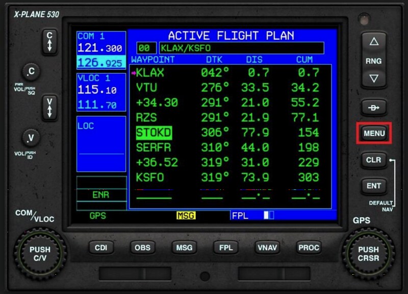
Press the MENU button (19). The system will pop up available options.
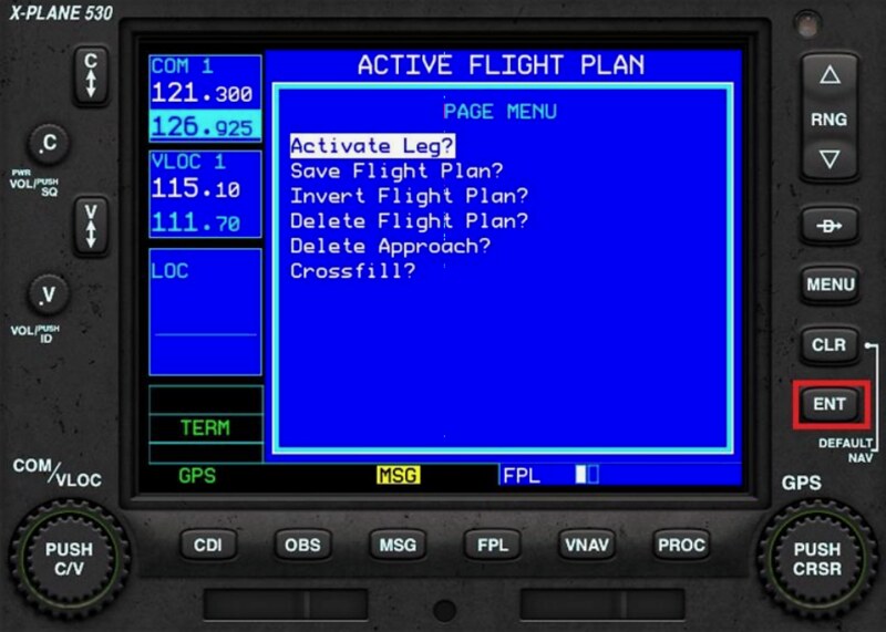 Use the small adjustment knob (14) to select ‘Activate Leg’ and press the ENT button.
The G530 will skip intermediate Waypoints and fly directly to the target.
Use the small adjustment knob (14) to select ‘Activate Leg’ and press the ENT button.
The G530 will skip intermediate Waypoints and fly directly to the target.
9 Activate Approach
When receiving approach clearance from ATC, the flight moves from the Cruise (ENR) or Terminal (TERM) phase to the Approach (APR) phase.
In FPL mode on the current flight status page, press the Procedures (PROC) button.
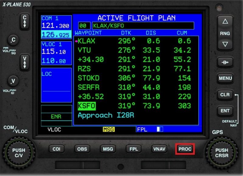 This brings up the Procedures menu.
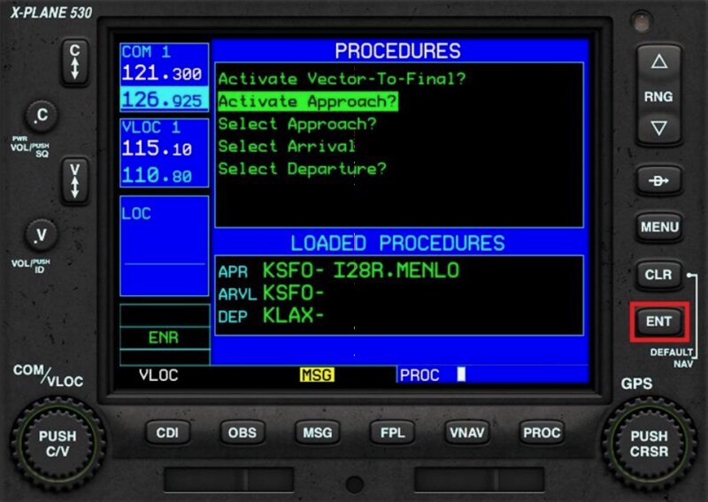 Use the small adjustment knob (14) to select ‘Activate Approach’ and press the ENT button.
The G530 will enter the approach phase and fly towards the Initial Approach Fix (IAF).
Use the small adjustment knob (14) to select ‘Activate Approach’ and press the ENT button.
The G530 will enter the approach phase and fly towards the Initial Approach Fix (IAF).
If ATC does not issue a standard approach procedure but instead provides radar vectors, You can select the ‘Activate Vector-To-Final’ option in the Procedures menu above. In this case, the G530 will delete the approach procedure Waypoints And display the course to the Final Approach Fix (FAF).
10 Loading Flight Plan Files X-Plane 11 supports the following three flight plan file types:
- fms files: XP-specific format used since X-Plane 9, containing only Waypoint information.
- flp files: Format compatible with other flight simulation software, containing Waypoint information.
- fml files: X-Plane 11 specific files.
Press the Flight Plan (FPL) button and use the small adjustment knob (14) to select the “Flight Plan Catalog” page.
Press the multi-function button (15) to enter edit mode.
Use the small adjustment knob (14) to select the file you want to use, then press the ENT button.
11 OBS Function Using the OBS function displays the target interception radial on the screen, helping the pilot better understand the navigation route.
For example, when flying from KLAX to KTOA, the pilot wants to intercept via the 360-degree radial of KTOA.
However, KTOA is currently at a 130-degree Bearing from the aircraft.
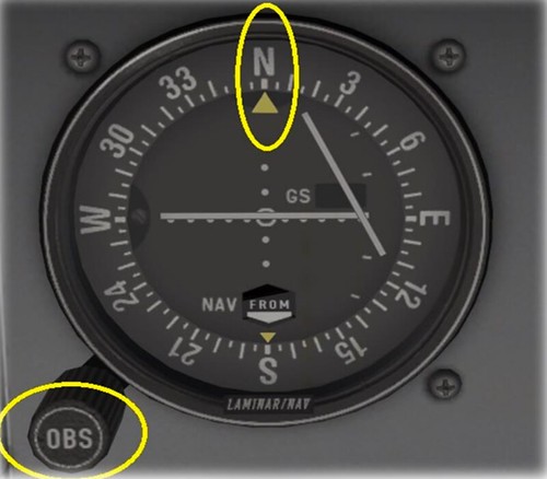
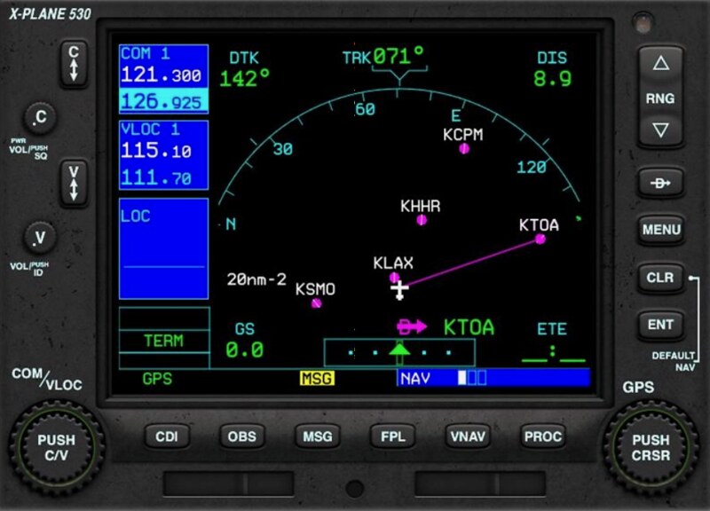 So the pilot adjusts the OBS to 360 degrees and can see the CDI deviation.
 Back on the GNS530, press the Omni Bearing Selector (OBS) button (9).
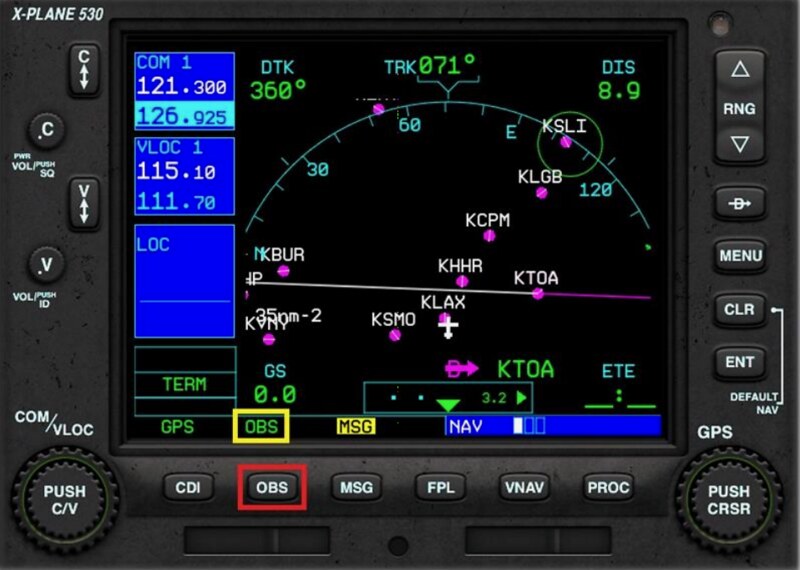 The TO 360-degree radial is displayed as a magenta line,
And the FROM 360-degree radial is displayed as a white line.
The bottom status bar displays “OBS”.
This makes understanding the aircraft’s orientation and future piloting easier.
The TO 360-degree radial is displayed as a magenta line,
And the FROM 360-degree radial is displayed as a white line.
The bottom status bar displays “OBS”.
This makes understanding the aircraft’s orientation and future piloting easier.
12 Suspend Mode When OBS is active, if the aircraft flies over the navigation station, The system will enter Suspend mode, and the bottom status bar will display “SUSP”.
When OBS is not active, if the aircraft enters a holding pattern,
Or if the aircraft executes a Missed Approach during a procedure approach,
The system will also enter Suspend mode, and the bottom status bar will display “SUSP”.
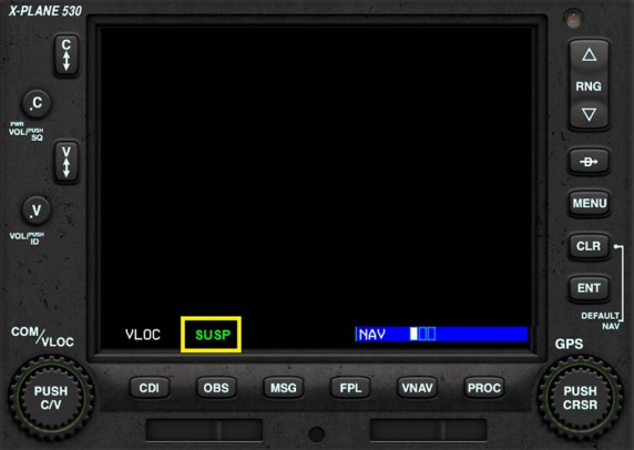
The pilot can continue the approach in SUSP mode, Or click the OBS button to explicitly exit SUSP mode. The G530 will automatically display the first nav point of the missed approach procedure.
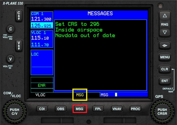
13 System Messages
Pressing the MSG button displays system notification messages on the screen.
The bottom status bar displays “MSG”.
14 Autopilot The G530 is a navigator. If it is used as the main GPS navigation equipment, it can link with the aircraft’s autopilot. However, the autopilot on each aircraft is different, so you need to understand how to use it individually. Taking the King Air C90B in X-Plane 11 as an example: First, press the CDI button (8) on the G530 to activate GPS mode instead of VLOC mode.
Then press the AP button on the autopilot, followed by the NAV button.
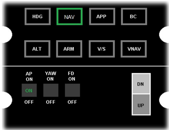 The aircraft will now be automatically controlled by the autopilot.
Other Reference Materials 1 GPS (430-530) Tutorials 2 Actually, there are X-Plane G530 Manual.pdf and X-Plane G430 Manual.pdf in the X-Plane 11/Aircraft/Laminar Research/Cessna 172SP directory. You can look for them.