Let's Play with Boeing 777 Cold & Dark Start
Last time, a netizen asked about cold engine starting, and I remembered I had some screenshots from when I was testing the VMAX-777-Pro Boeing 777 Worldliner Professional. So, I decided to put together a quick guide based on the 777 Pilot’s Handbook included with the addon. This manual is authorized by Boeing to the software developer, so its authority is beyond doubt.
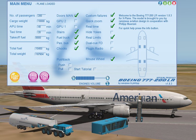
First, let’s look at the main menu of this 777 addon. This is where fueling is done.
Below, we will proceed with the startup following the Normal Procedure in the manual. Please refer to the manual for details; my screenshot steps aren’t quite complete.
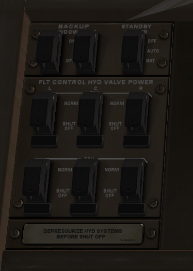
Preflight Procedure - First Officer Overhead panel check, from left to right, top to bottom Overhead maintenance panel ……………….Check Verify: • all guards closed • flight control VALVE CLOSED lights extinguished.
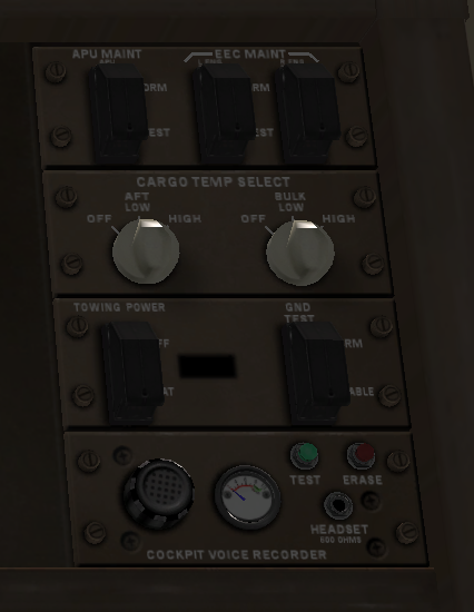
 CARGO TEMPERATURE selectors - As required
ADIRU switch ………………………….. ON
Verify ON BAT and OFF lights extinguished.
Note: A complete ADIRU alignment is recommended if the total
time in the navigation mode is expected to exceed 24 hours.
THRUST ASYMMETRY COMPENSATION
switch …………………………………AUTO
Verify OFF light extinguished.
PRIMARY FLIGHT COMPUTERS
DISCONNECT switch ………………………AUTO (guarded position)
Verify DISC light extinguished.
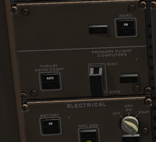
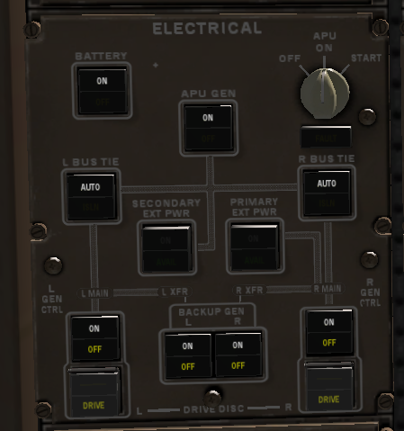
ELECTRICAL panel……………………….. Set
BATTERY switch - ON
Verify OFF light extinguished.
IN-FLIGHT ENTERTAINMENT SYSTEM/PASSENGER
SEATS POWER and CABIN/UTILITY POWER switches - ON
Verify OFF lights extinguished.
APU GENERATOR switch - ON
Verify OFF light extinguished.
APU selector - START
Verify FAULT light extinguished.
BUS TIE switches - AUTO
Verify ISLN lights extinguished.
GENERATOR CONTROL switches - ON
OFF and DRIVE lights remain illuminated until respective engine is
started.
BACKUP GENERATOR switches - ON
OFF lights remain illuminated until respective engine is started.
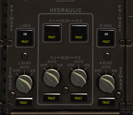
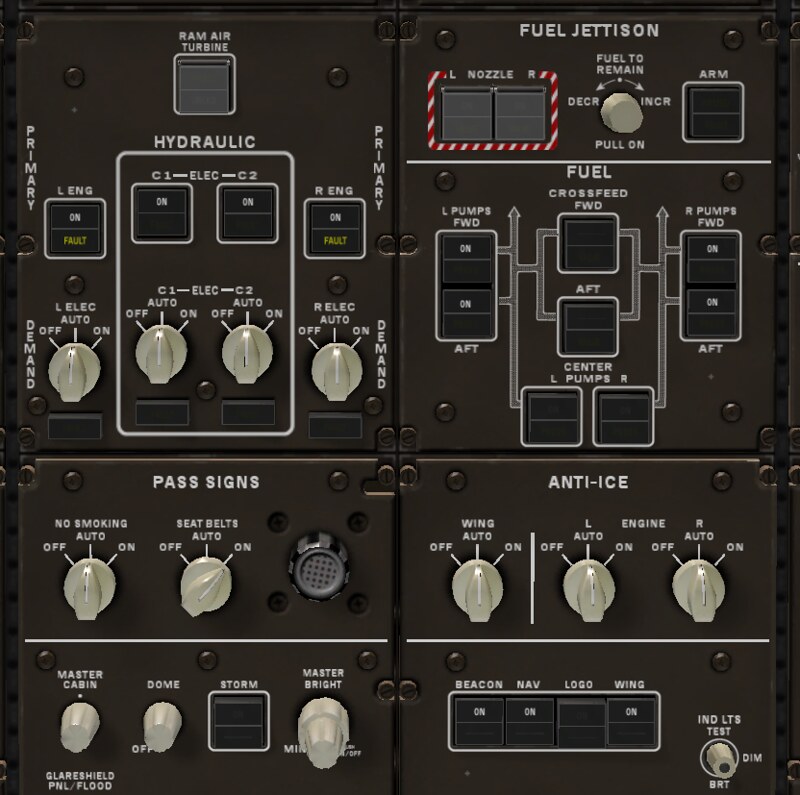
HYDRAULIC panel ………………………..Set
LEFT and RIGHT PRIMARY pump switches - ON
Left and right primary pump ON light remains in off position until
respective engine is started.
C1 and C2 PRIMARY pump switches - OFF
Verify FAULT lights illuminated.
DEMAND pump selectors - OFF
Verify FAULT lights illuminated.
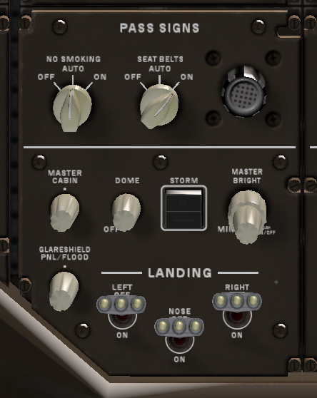
PASSENGER SIGNS panel …………………. Set
NO SMOKING selector - AUTO or ON
SEAT BELTS selector - ON
Lighting panel ……………………….. Set
DOME light control - Adjust
STORM light switch - As desired
MASTER BRIGHTNESS control - Adjust
Glareshield light controls - Mid position
LANDING light switches - OFF
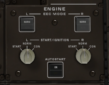
ENGINE panel………………………..Set
EEC MODE switches - NORM
START/IGNITION selectors - NORM
AUTOSTART switch - ON
Verify OFF light extinguished.
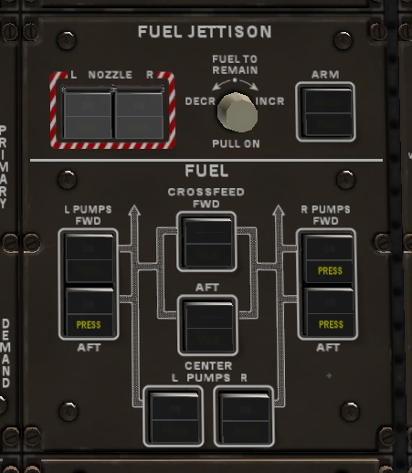
FUEL JETTISON panel ……………………..Set
FUEL JETTISON NOZZLE switches - Off
Verify VALVE lights extinguished.
FUEL TO REMAIN selector - IN
FUEL JETTISON ARM switch - Off
Verify FAULT light extinguished.
FUEL panel …………………………….Set
CROSSFEED switches - OFF
Verify VALVE lights extinguished.
FUEL PUMP switches - OFF
Left and right pump PRESS lights are illuminated.
Left forward pump PRESS light is extinguished if the APU is running.
Both center pump PRESS lights are extinguished.
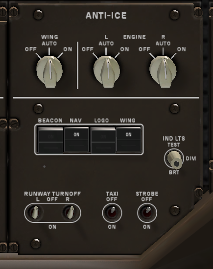
ANTI-ICE panel………………………….Set
WING anti-ice selector - AUTO
ENGINE anti-ice selectors - AUTO
Lighting panel …………………………Set
BEACON light switch - OFF
NAVIGATION light switch - ON
LOGO light switch - ON during nighttime operation
WING light switch - As required
INDICATOR LIGHTS switch - As desired
RUNWAY TURNOFF, TAXI, and STROBE light switches - OFF
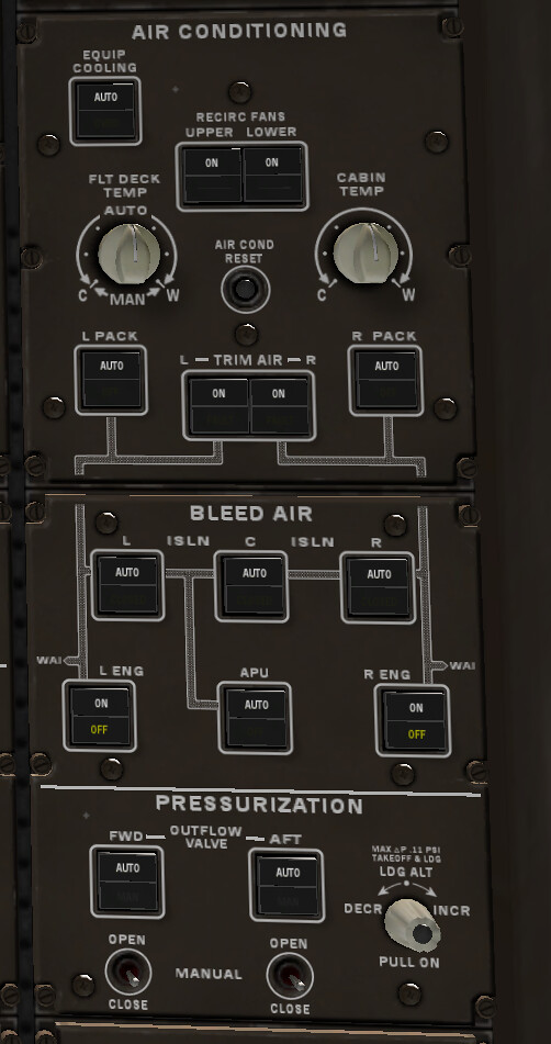
 AIR CONDITIONING panel ………………………. Set
EQUIPMENT COOLING switch - AUTO
Verify OVRD light extinguished.
RECIRCULATION FANS switches - ON
FLIGHT DECK TEMPERATURE control - AUTO (mid position)
CABIN TEMPERATURE control - Mid position
PACK switches - AUTO
Verify OFF lights extinguished.
TRIM AIR switches - ON
Verify FAULT lights extinguished.
BLEED AIR panel ………………. Set
Bleed ISOLATION switches - ON
Verify CLOSED lights extinguished.
ENGINE bleed switches - ON
Verify OFF lights illuminated.
APU bleed switch - AUTO
Verify OFF light extinguished.
PRESSURIZATION panel …………………. Set
OUTFLOW VALVE switches - AUTO
Verify MAN lights extinguished.
LANDING ALTITUDE selector - IN
AIR CONDITIONING panel ………………………. Set
EQUIPMENT COOLING switch - AUTO
Verify OVRD light extinguished.
RECIRCULATION FANS switches - ON
FLIGHT DECK TEMPERATURE control - AUTO (mid position)
CABIN TEMPERATURE control - Mid position
PACK switches - AUTO
Verify OFF lights extinguished.
TRIM AIR switches - ON
Verify FAULT lights extinguished.
BLEED AIR panel ………………. Set
Bleed ISOLATION switches - ON
Verify CLOSED lights extinguished.
ENGINE bleed switches - ON
Verify OFF lights illuminated.
APU bleed switch - AUTO
Verify OFF light extinguished.
PRESSURIZATION panel …………………. Set
OUTFLOW VALVE switches - AUTO
Verify MAN lights extinguished.
LANDING ALTITUDE selector - IN
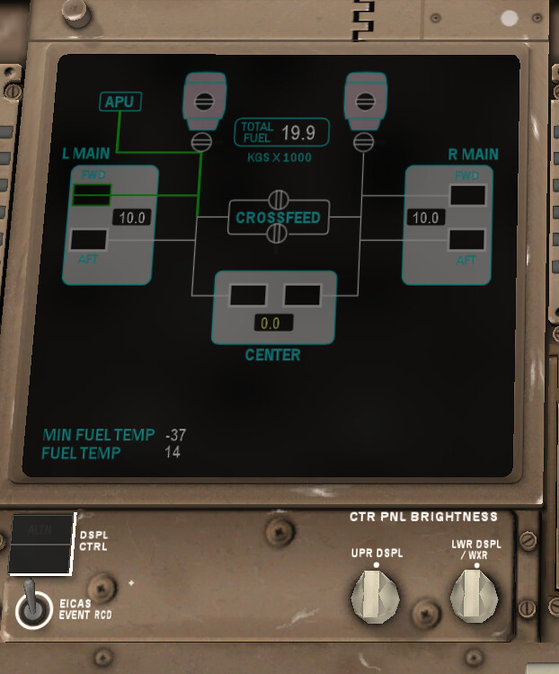
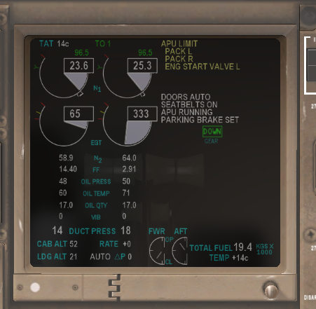
By this time, the fuel should be finished loading. Check if the values are correct.
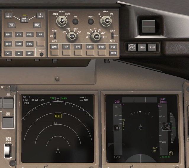
Next is the MCP and EFIS
Right FLIGHT DIRECTOR switch ……………. ON
Display select panel ……………………Set
LWR CTR display switch - Push
Right EFIS control panel …………………Set
MINIMUMS reference selector - As desired
MINIMUMS selector - Minimum shall be blanked
FLIGHT PATH VECTOR switch - Flight path vector shall be
blanked
METERS switch - Meters indication shall be blanked except when
meters information is required.
BAROMETRIC reference and BAROMETRIC selectors - Set
Set the local altimeter setting on the PFD.
VOR/ADF switches - As desired
ND mode selector - MAP
Use ND expanded map mode for all phases of flight.
ND CENTER switch - Select expanded display
ND range selector -Select:
ND TRAFFIC switch - Select ON
Map switches - As desired
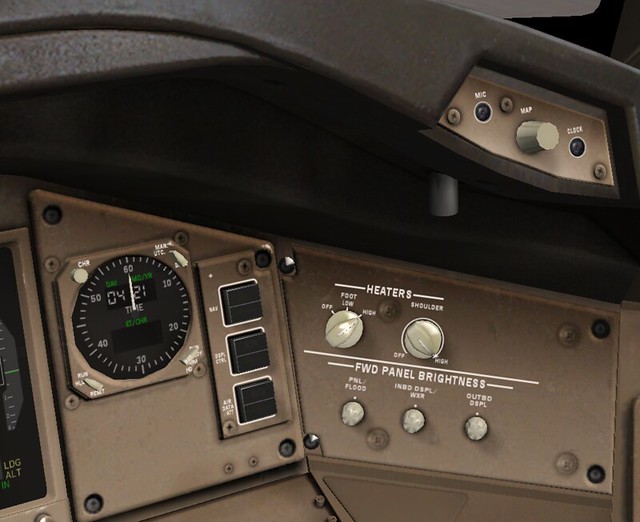
I won’t post the specifics for heaters and brightness here.
Right PFD …………………………Check
Flight mode annunciations - Verify:
• autothrottle mode is blank
• roll mode is TO/GA
• pitch mode is TO/GA
• AFDS status is FLT DIR.
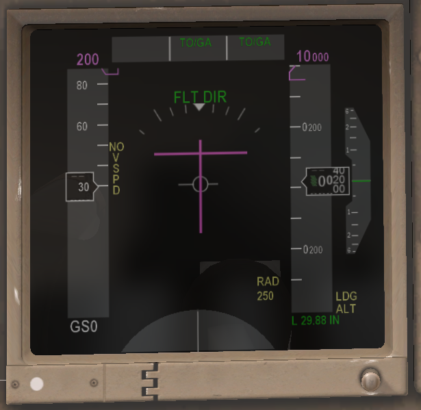
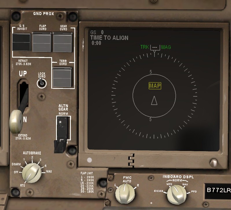
Right ND ………………………….Check
Verify expanded map mode displayed.
Right INBOARD DISPLAY selector ……….. MFD
FMC Selector ………………………. AUTO
Landing gear panel ………………….. Set
GROUND PROXIMITY light - Extinguished
Ground proximity FLAP OVERRIDE switch - Off
Ground proximity GEAR OVERRIDE switch - Off
Ground proximity TERRAIN OVERRIDE switch - Off
Landing gear lever - DN
ALTERNATE GEAR switch - NORM (guarded position)
AUTOBRAKE selector - RTO
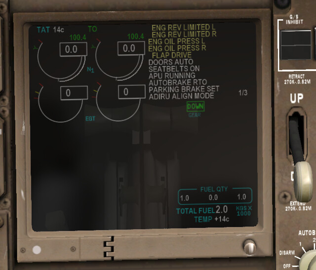
 EICAS display ………………………. Check
Indications - Normal. Verify:
• primary engine indications display existing conditions
• no exceedance values are displayed.
EICAS display ………………………. Check
Indications - Normal. Verify:
• primary engine indications display existing conditions
• no exceedance values are displayed.
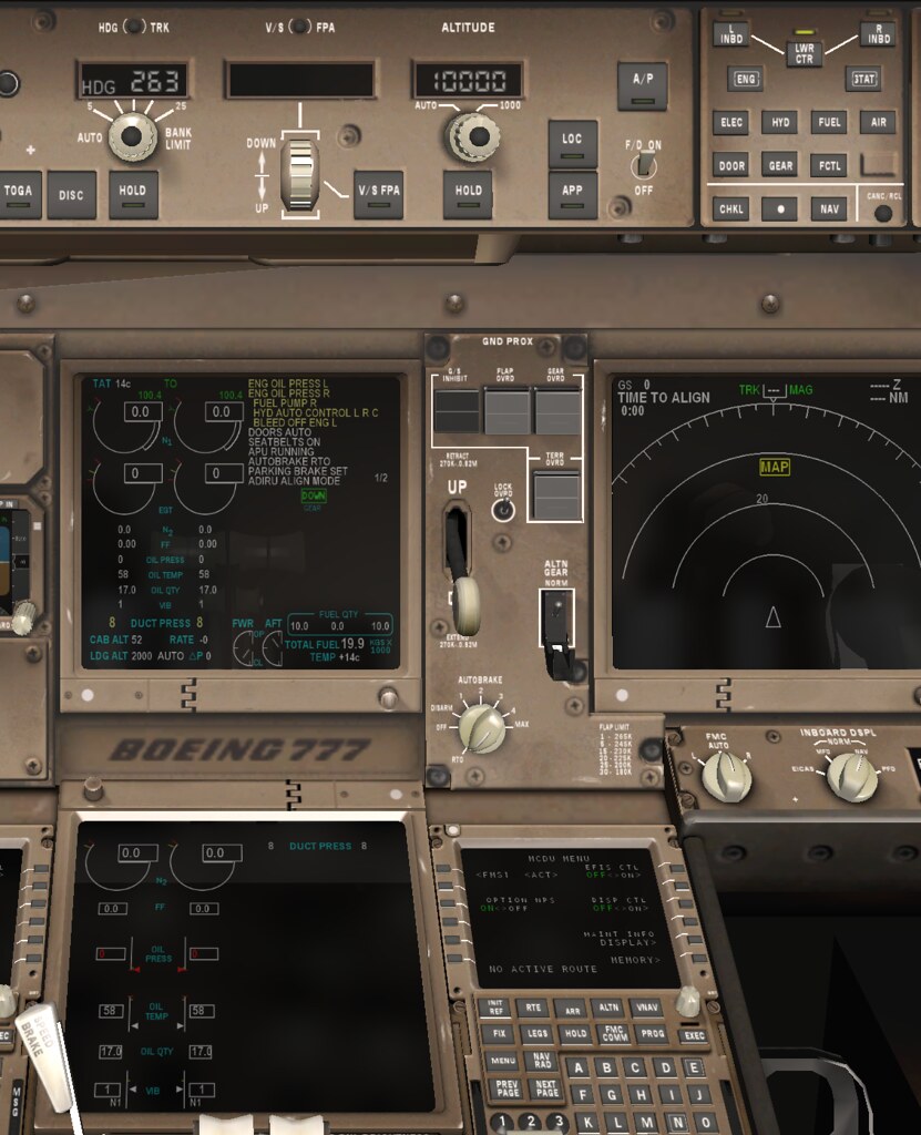
 MFD ……………………………….. Check
Secondary ENGINE display switch - Push
Secondary ENGINE display - Verify:
• secondary engine indications display existing conditions
• no exceedance values are displayed.
MFD ……………………………….. Check
Secondary ENGINE display switch - Push
Secondary ENGINE display - Verify:
• secondary engine indications display existing conditions
• no exceedance values are displayed.
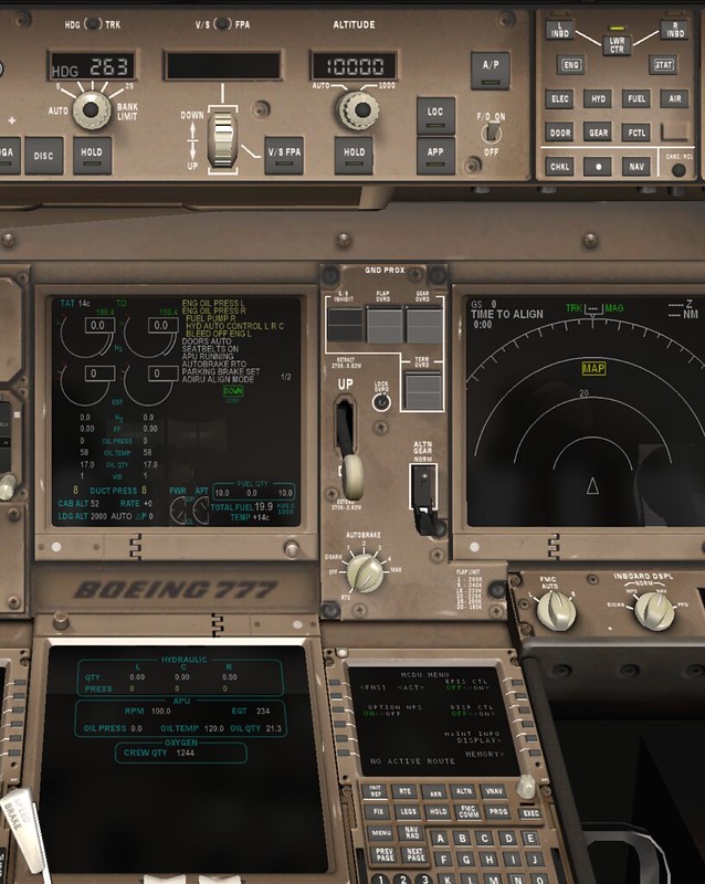
 STATUS display switch - Push
STATUS display - Verify:
• hydraulic quantities do not display RF
• oxygen pressure is sufficient for flight.
If any status message is displayed, refer to the Minimum Equipment
List and Dispatch Deviation Guide to determine if dispatch relief is
available.
STATUS display switch - Push
STATUS display - Verify:
• hydraulic quantities do not display RF
• oxygen pressure is sufficient for flight.
If any status message is displayed, refer to the Minimum Equipment
List and Dispatch Deviation Guide to determine if dispatch relief is
available.
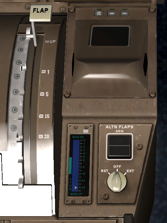
FLAP position indication and FLAP lever …. Agree
Flap position indication is blank when flaps are up.
ALTERNATE FLAPS panel ………………… Set
ALTERNATE FLAPS ARM switch - OFF
ALTERNATE FLAPS selector - OFF
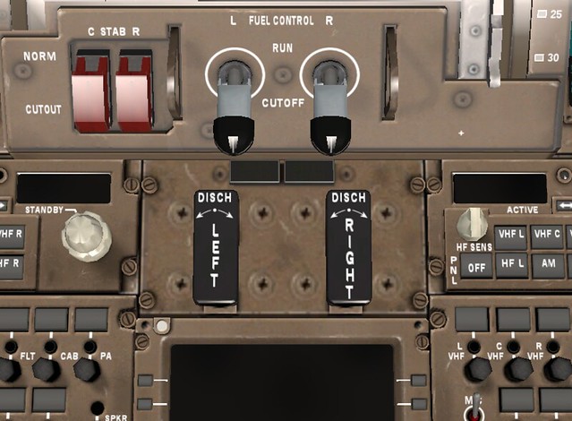
Engine fire panel ……………………. Set
ENG BTL 1 DISCH and ENG BTL 2 DISCH lights - Extinguished
Engine fire switches - In
Verify LEFT and RIGHT fire warning lights extinguished.
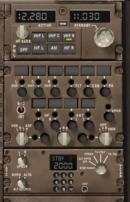
The radio communication equipment is also relatively simple, so I won’t post detailed screenshots.
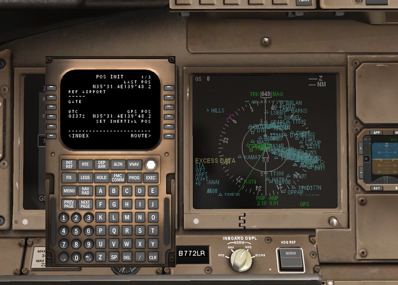
Next is the FMC CDU setup,
Right CDU ……………………………Set
INIT REF key - Push
INDEX line select key - Push
IDENT line select key - Push
IDENT page - Check
Verify active date current.
POS INIT line select key - Push
Verify time correct.
Inertial position - Enter
Enter inertial position using the most accurate latitude and
longitude.
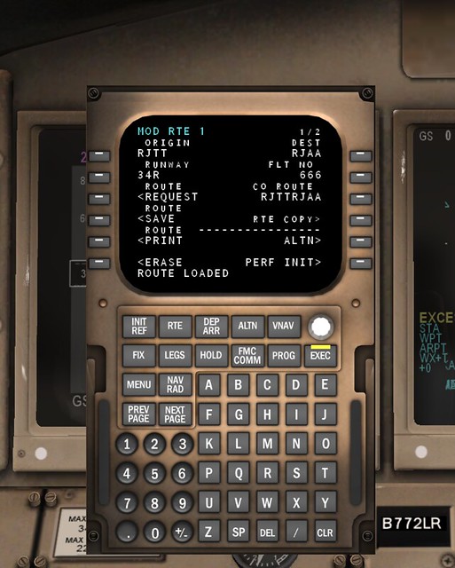
ROUTE line select key - Push
Enter:
• flight number
• route.
ACTIVATE line select key - Push
EXEC key - Push
DEP ARR key - Push
Select runway and SID.
ROUTE line select key - Push
Verify SID and route are correct.
EXEC key - Push
NAV RAD key - Push
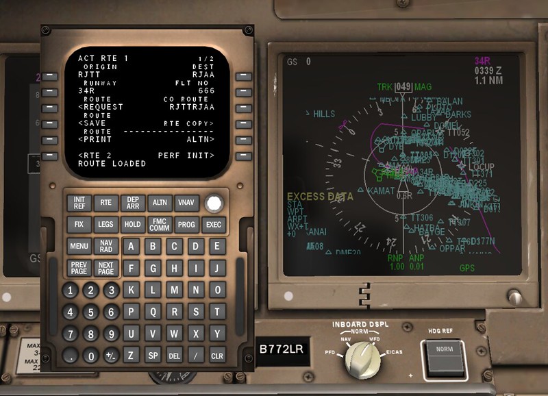
Set/verify navigation radio tuning. PERF INIT line select key - Push Enter: • fuel reserves • cruise altitude • cost index. Check and/or enter: • minimum fuel temperature value (enter freeze point temperature for the type of fuel being used if the correct value is not displayed) • cruise CG • step size values. TAKEOFF line select key - Push Enter takeoff flap setting. Check and/or enter: • acceleration height • engine-out acceleration height • thrust reduction point • runway wind component • runway slope • runway position value
Then comes Preflight Procedure - Captain. The content is basically the same.
Once complete, you can wait to enter the Before Start Procedure.
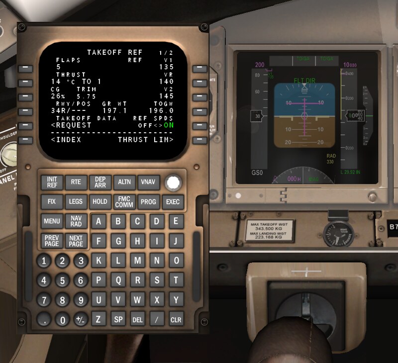
CDU………………………………. Set C
INIT REF key - Push
Verify fuel quantities agree:
• upload fuel quantity
• EICAS
• CDU.
Enter: zero fuel weight
THRUST LIM line select key - Push
Select takeoff thrust:
• full thrust
• assumed temperature derate.
TAKEOFF line select key - Push
Enter CG.
Select or enter takeoff speeds.
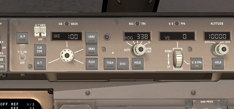
MCP…………………………. Set C
IAS/MACH selector - Rotate
Set V2 speed in the IAS/MACH window.
LNAV switch - As required
VNAV switch - Push
After obtaining pushback clearance, you can start the hydraulics and fuel.
HYDRAULIC panel……………..Set F/O
Note: Pressurize right system first to prevent fluid transfer between
systems.
Right DEMAND pump selector - AUTO
Verify FAULT light extinguished.
C1 and C2 PRIMARY pump switches - ON
Verify FAULT lights extinguished.
Note:With only a single ground power source available,
including the APU, the C2 PRIMARY pump will not run
if the C1 pump is selected ON. The C2 primary pump
FAULT light remains illuminated until an engine
generator is operating. The HYD PRESS PRI C2
message is inhibited.
Left, C1, and C2 DEMAND pump selectors - AUTO
Verify FAULT lights extinguished.
FUEL panel ………………………..Set F/O
LEFT and RIGHT FUEL PUMP switches - ON
Verify PRESS lights extinguished.
If center tank contains fuel:
CENTER FUEL PUMP switches - ON
Verify PRESS lights extinguished.
Note: One or both PRESS lights may not be extinguished due to
load shedding. Indications will be normal after engine
start.
BEACON light switch …………………..ON F/O
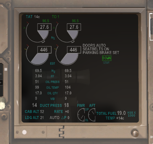
After pushback, you can start the engines and execute the Engine Start Procedure. First Officer Position ____ START/ IGNITION selector to START.
Captain Position ____ FUEL CONTROL switch to run.
Fin.