GBAS and GLS
GBAS: Ground-Based Augmentation Systems, a satellite navigation augmentation system where user receivers receive navigation enhancement information from ground transmitters. It consists of three parts: a space navigation satellite constellation system, a ground augmentation system, and an airborne receiver system.
GLS: GBAS Landing System, a satellite landing system based on GBAS navigation performance enhancement. It includes the GBAS system enabling precision approach and landing, as well as related aircraft functions.
The traditional Instrument Landing System (ILS) relies on technology from the 1930s. It provides approach and landing guidance to aircraft through multiple pairs of antennas installed for each Runway, thereby helping aircraft land accurately on airport Runways.
The disadvantages of ILS include susceptibility to interference, such as the case of ILS signal interference at Taoyuan Airport previously introduced on this site; high maintenance costs, as each Runway requires dedicated antennas; a system lifespan of only a little over ten years, requiring maintenance updates on average every six months— this site has previously covered the inspection and verification of equipment at Kansai Airport; furthermore, if the system is damaged, reinstallation takes a long time, for example, in the reactivation of Category III Blind Landing at Hiroshima Airport, the antenna damaged by the Asiana Airlines Flight OZ162 took half a year to repair.
The new generation GBAS system utilizes GPS positioning,
allowing a single system to provide guidance for multiple Runways at an airport.
This significantly reduces limitations regarding Descent angles, approach paths, and weather conditions.
The more accurate information gained allows air traffic control to arrange aircraft takeoffs and landings more flexibly, ultimately increasing airport traffic flow.

GBAS uses only one channel, and all aircraft within a radius of 23 nautical miles can receive the data required for landing. A multi-mode receiver integrated with a GPS antenna on the aircraft processes the data, displays it on the cockpit display, and fuses it into the automatic flight control system.
Compared with the traditional Instrument Landing System, the GBAS satellite navigation landing system supports approach procedures with multiple angles and paths. It allows aircraft to bypass obstacles and sensitive areas, thereby greatly improving flight safety.
A magazine on hand once introduced data from GBAS tests conducted by ANA and JAL using Boeing 787 airliners at Osaka Kansai Airport in 2011 and 2012.
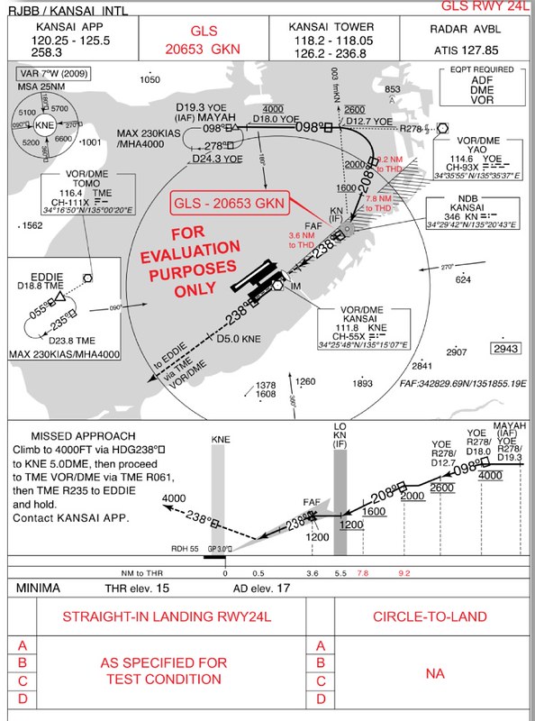
The prototype approach chart used at the time is shown below.
The procedure is GLS RWY24L. You can see that the FMS input is not the ILS VHF frequency,
but the 5-digit code “20653 GKN”, representing the GBAS system ID number.
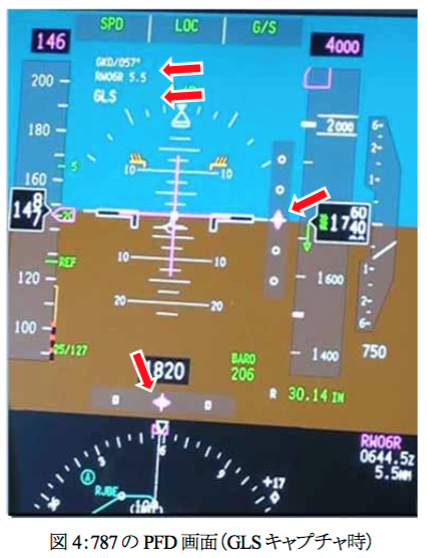
The image below shows the PFD display when a Boeing 787 performs a GLS approach on Runway 06R.
You can see the indication at the red arrow in the upper part. After capturing the GBAS signal, it displays a Heading of “057” degrees.
At this point, the distance to the Runway is “5.5” nautical miles, and the approach mode is “GLS”.
Other operational methods are no different from the existing ILS.
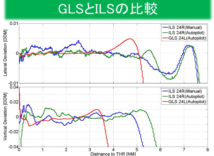
The test results are shown in the figure below: red represents GLS automatic landing,
blue represents ILS manual landing, and green represents ILS automatic landing data.
It can be seen that compared with ILS landings,
after capturing the signal, the horizontal and vertical deviations of GLS are basically close to 0,
and the changes are much smoother, making the flight very stable.
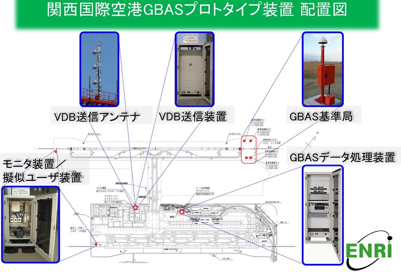
The equipment installed at Osaka Kansai Airport this time is shown below. You can see the VDB antenna installed on the Tower,
and the 4 GBAS ground stations installed near the threshold of Runway 24R.
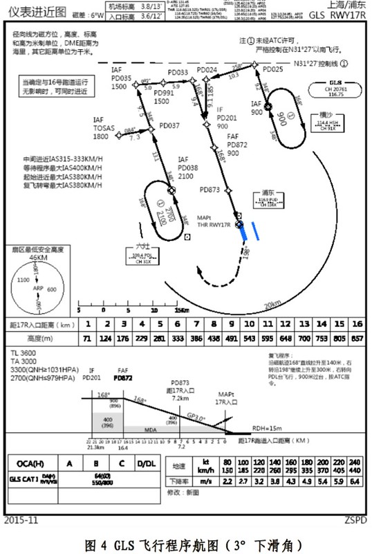
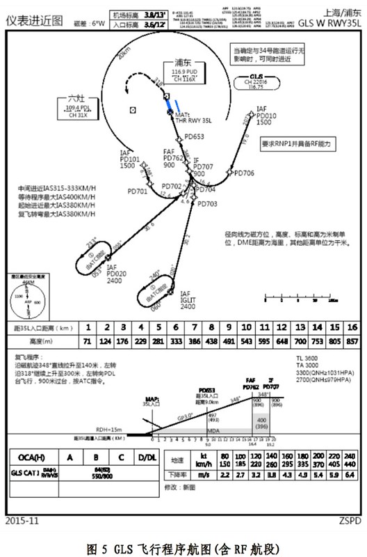
In April 2015, the Civil Aviation Administration of China (CAAC) completed the first GLS demonstration verification flight in the country at Shanghai Pudong Airport.
According to CAAC data, the image in the bottom right of the figure below should be the PFD of an Airbus aircraft,
with GLS symbols displayed in the bottom right corner.

For reference, the approach chart is also attached. You can see the notations GLS CH22016 116.75 and GLS CH20761 116.75.
So, although the Runways and codes are different, the frequency used is the same 116.75MHz.
Reference 1 Reference 2 Satellite Landing System (GLS) Operational Approval Guide - Civil Aviation Administration of China
End