Introduction to Visual Docking Guidance System
As everyone knows, after an aircraft lands, it either docks at the Jet Bridge, requiring ground marshals to visually estimate the distance and guide the pilot by holding up yellow signs; or it uses the Visual Docking Guidance System, where the pilot controls the aircraft to taxi into the parking spot based on the instructions on the display screen ahead.
I recently saw the system manual for Haneda Airport and found it quite interesting, so I decided to briefly record it.
The Visual Docking Guidance System consists of a display screen and a laser scanner that measures the aircraft’s distance. The system can detect and analyze the aircraft model, track the aircraft position using lasers, and display the results on the screen. The information on the screen mainly includes: Aircraft Type Information on deviation from the center taxi line Distance to the parking spot
When ground operations personnel complete the input and verify the aircraft type information via the manual control panel, the system initiates a self-check and begins continuous scanning.
When no approaching aircraft is detected, the upper part of the screen displays the aircraft type information, while the lower part displays continuously upward-moving yellow arrows, as shown in Figure 1 below.
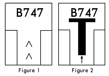 When taxiing into the gate, the pilot sees this signal and knows the system is active and waiting for the aircraft, so the pilot begins to maneuver the aircraft to complete the taxi-in operation.
When the laser detects an approaching aircraft, the system starts to display a T-shaped symbol in the center of the screen. Below the T-shape is a small arrow pointing upwards, as shown in Figure 2 above.
When the aircraft approaches within 12 meters of the stopping position, the system begins to identify if the aircraft model matches the one previously entered. If the information is consistent, the system continues to provide guidance. However, if the system detects a mismatch, the upper part of the screen will alternately flash the error message “STOP-ID-FAIL”, while two red warning squares appear in the center of the screen.
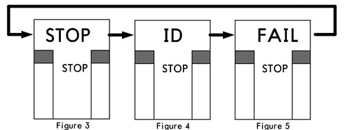 Upon seeing this message, the pilot must immediately stop the aircraft’s forward movement.
If the system detects that the aircraft is taxiing too fast, the screen displays the word “SLOW”.
 This reminds the pilot to reduce speed to prevent the aircraft from overshooting the parking spot.
If the system detects that the aircraft has deviated from the center taxi line, a small yellow arrow pointing upwards will appear on the lower left or right side of the T-shape on the screen, indicating whether the aircraft’s current position has deviated to the left or right of the center line. At the same time, a continuously flashing red cursor appears at the top of the screen, pointing to the right or left, reminding the pilot to adjust the Heading to the right or left.
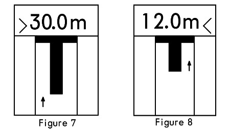
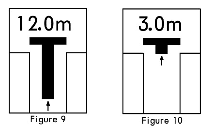
When the aircraft enters within 30 meters of the parking spot, the screen begins to display distance information. For every meter closer, the data updates in meters, such as 30.0m, 7.0m, etc. When the aircraft is within 2 meters of the parking spot, the figures on the screen update in increments of 0.2 meters for every 0.2 meters closer.
When the aircraft is within 16 meters of the parking spot, the length of the vertical line of the T-shaped symbol on the screen also begins to shorten continuously. This display not only visually represents the distance to the stopping point but also shows the rate of closure, helping the pilot better control taxi speed. The vertical line length decreases by one segment for every 0.5 meters closer.
When the aircraft arrives at the parking spot, the screen displays the word “STOP”, and two red squares appear on both sides in the center, as shown below.

When the aircraft is correctly parked at the dock, the screen displays the word “OK” for several seconds, as shown in Figure 12 below.
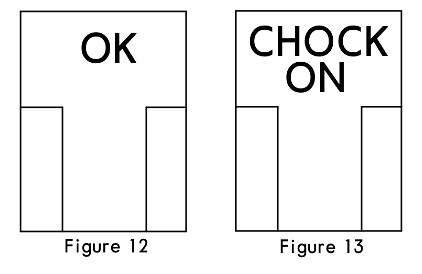
When ground personnel insert the landing gear down lock pin and turn on the system’s “CHOCK ON” switch, the screen simultaneously displays “CHONCK ON”, notifying the pilot that the operation is complete, as shown in Figure 13 below.
This marks the end of the entire guidance process.
If the aircraft stops past the correct position, the system will display a “TOO FAR” message.

Below, I will introduce other error messages of the system.
In addition to messages like STOP and FAIL, if the system displays “WAIT”, the pilot must also immediately stop taxiing and wait for the next operational instruction.
If adverse weather such as heavy fog, rain, or snow occurs, it may affect the Visibility of the Visual Docking Guidance System. In this case, the system will temporarily display the word “SLOW”. The pilot needs to ensure the aircraft does not taxi past the Jet Bridge position and wait for the system to scan the aircraft and resume displaying the T-shape before continuing operations.
If the system malfunctions and cannot work normally, the screen will go black, displaying only two red squares on the left and right sides of the center.
In summary, the aircraft Visual Docking Guidance System not only reduces the workload of ground personnel, but airport operations management departments can also calculate the occupancy time of each parking spot through the system. This allows for scheduling more takeoffs and landings and improving the overall equipment level of the airport. Therefore, the use of this system can effectively improve the utilization rate of parking spot resources, reduce flight delay rates, avoid errors caused by manual guidance, effectively save operating costs, and comprehensively improve the management level of the airport apron.
End