Title: Airliner Cockpit Exploration 2.2 Standard Instrument Departure SID
In the previous section 5 Minutes Before Departure, it was mentioned that Air Traffic Control notified the pilot to use the Moriya 7 Departure procedure. So, what exactly is a Departure procedure?
Airplanes flying in the air are not without traffic rules. Because there are numerous airlines, especially at major airports where planes take off and land every few minutes. Similar to ground traffic, if there were no set of traffic rules to manage it, aircraft operations would be extremely dangerous. Therefore, many routes are established in the air. Although we cannot see these routes with the naked eye like roads on the ground, pilots must strictly follow the regulations to execute their flight missions. The routes and procedures set up for departing aircraft are called Standard Instrument Departures (SIDs).
An SID is a series of pre-established routes that guide the aircraft from takeoff all the way to the Departure point. This Departure point is the first navigation waypoint of the air route in the flight plan. In other words, a Standard Instrument Departure is a procedure that guides the aircraft out of the Terminal Control Area (TMA). The MORIYA mentioned in the previous section regarding the MORIYA Departure procedure is a Departure point when leaving Haneda Airport, and it is a navigation point located in Moriya, Ibaraki Prefecture.
An airport may have many different Standard Instrument Departures. Each Runway has different departure procedures that guide aircraft to different Departure points. As for which Departure point an aircraft is heading to, it depends on the Runway direction used for takeoff and the Destination and air route in the flight plan.
This procedure includes the Heading, altitude, Turn locations, time, etc., for the aircraft leaving the airport. ATC only needs to control the separation of the aircraft, and the pilot can fly the aircraft out of the airport and enter the airway by following this procedure.
The Departure procedure is composed of many waypoints and navigation points. These waypoints can be marked by latitude and longitude, or by their position relative to navigation aids. For example, giving a radial line and distance from a VOR can identify a point near the VOR. At the same time, climb information will be marked on the departure route, meaning the pilot must climb to or above a certain altitude at a certain point.
When the aircraft reaches the Departure point, the entire Departure procedure is terminated.
Standard Instrument Departures are established to ensure the safety of aircraft after takeoff and to facilitate the handling of departing aircraft, while also minimizing noise over residential areas as much as possible.
Below, let’s look at the specific regulations for the actual Haneda Airport Moriya 7 Departure procedure:
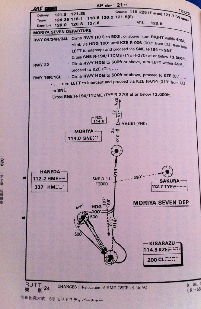
The top of the chart lists the various frequencies required for Air Traffic Control, such as Delivery at 121.8 and 121.85 MHz, Ground Control at 118.25 and 121.7 MHz, Tower at 124.35 118.1 118.8 MHz, etc.
The text section and chart at the bottom of the figure specifically explain the departure procedure. For example, when taking off from Runway 16R or 16L, First, Climb along the Runway direction to above 500 feet, and fly to the KZE (KISARAZU) navigation point in the bottom right corner of the chart, Then Turn left to Heading 14 (basically close to due north) and fly to the SNE (MORIYA) navigation point. MORIYA is a VOR station. Here, the chart indicates that there is an altitude restriction 11 nautical miles ahead of MORIYA, meaning you must fly at or below 13,000 feet (approximately 3,300 meters).
VOR in Chinese is called VHF Omni-directional Range. It is an international standard radio navigation equipment stipulated by the International Civil Aviation Organization (ICAO). The VOR receiver on the aircraft receives the reference phase signal and variable phase signal transmitted by the VOR ground station. By comparing the phase difference between the two signals, the aircraft’s radial方位 relative to the ground VOR station (i.e., the aircraft’s magnetic bearing QDR) is obtained. This information is indicated on the indicator for the pilot to determine the aircraft’s position and guide the aircraft’s navigation.
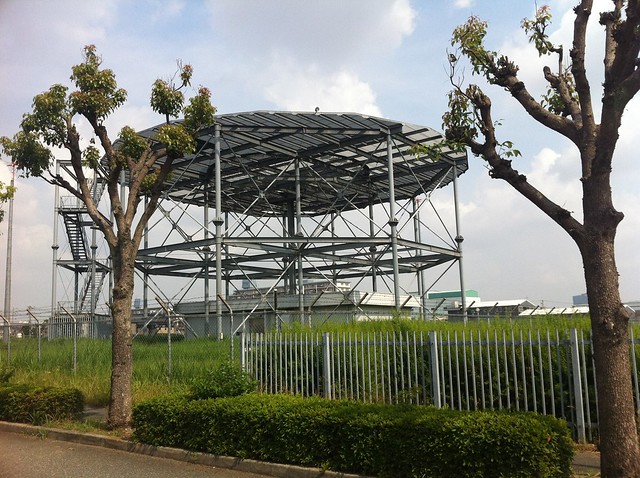
The picture below is a photo of the Oyad VOR ground station I took at Oyad Airport in Osaka. You can see its structure is quite simple.
The VOR indicator on a small aircraft is shown in the figure below. Image source: wikipedia:
 When using it, the pilot first tunes the navigation receiver’s frequency to that VOR station’s frequency, such as 114.0 MHz for MORIYA.
Then adjust the OBS knob to point to the desired Heading. If the aircraft is currently facing the direction of the VOR station,
The needle on the VOR indicator will appear in the center position as shown in the figure above.
When using it, the pilot first tunes the navigation receiver’s frequency to that VOR station’s frequency, such as 114.0 MHz for MORIYA.
Then adjust the OBS knob to point to the desired Heading. If the aircraft is currently facing the direction of the VOR station,
The needle on the VOR indicator will appear in the center position as shown in the figure above.
Prev: 5 Minutes Before Departure TOC: Table of Contents Next: Push Back from Gate and Start Engine
End